Deepwater Drilling Tube Support Device While Drilling and Design Method of Running Parameters

A support device and deep-water drilling technology, applied in drilling equipment, support devices, earthwork drilling and production, etc., can solve problems such as conduit inclination, mud line backing plate erosion, unfavorable cementing and drilling operations, etc., to reduce end resistance, The effect of improving bending moment resistance

Active Publication Date: 2018-08-10
CHONGQING UNIVERSITY OF SCIENCE AND TECHNOLOGY
View PDF9 Cites 0 Cited by
  • Summary
  • Abstract
  • Description
  • Claims
  • Application Information

AI Technical Summary

Problems solved by technology

[0003] In order to prevent the sinking and inclination of the conduit, at present the main methods are to increase the outer diameter and wall thickness of the conduit, add a mud line backing plate, and use specific anti-settlement tools to control the sinking and inclination of the conduit, but there are certain technical defects: excessive A large increase in the outer diameter and wall thickness of the conduit will directly lead to an increase in the size of the annulus between the conduit and the surface casing, which is not conducive to cementing and drilling operations; after adding the mudline backing plate, it is easy to cause erosion on one side of the mudline backing plate, Causing the catheter to tilt more severely
Using some underwater wellhead anti-instability devices can prevent the sinking of the conduit, but it is limited to the prevention of sinking after the conduit is installed in place, and is limited to the spraying method, which is not suitable for drilling, sinking and solidifying in hard formations. well; and this type of anti-instability device is set on the upper part of the conduit, and the conduit is fixedly connected by thread or welding, and cannot play the role of support while drilling

Method used


Image

  • Deepwater Drilling Tube Support Device While Drilling and Design Method of Running Parameters
  • Deepwater Drilling Tube Support Device While Drilling and Design Method of Running Parameters
  • Deepwater Drilling Tube Support Device While Drilling and Design Method of Running Parameters

Examples


Embodiment Construction

[0047] Below in conjunction with accompanying drawing and embodiment the present invention will be further elaborated:

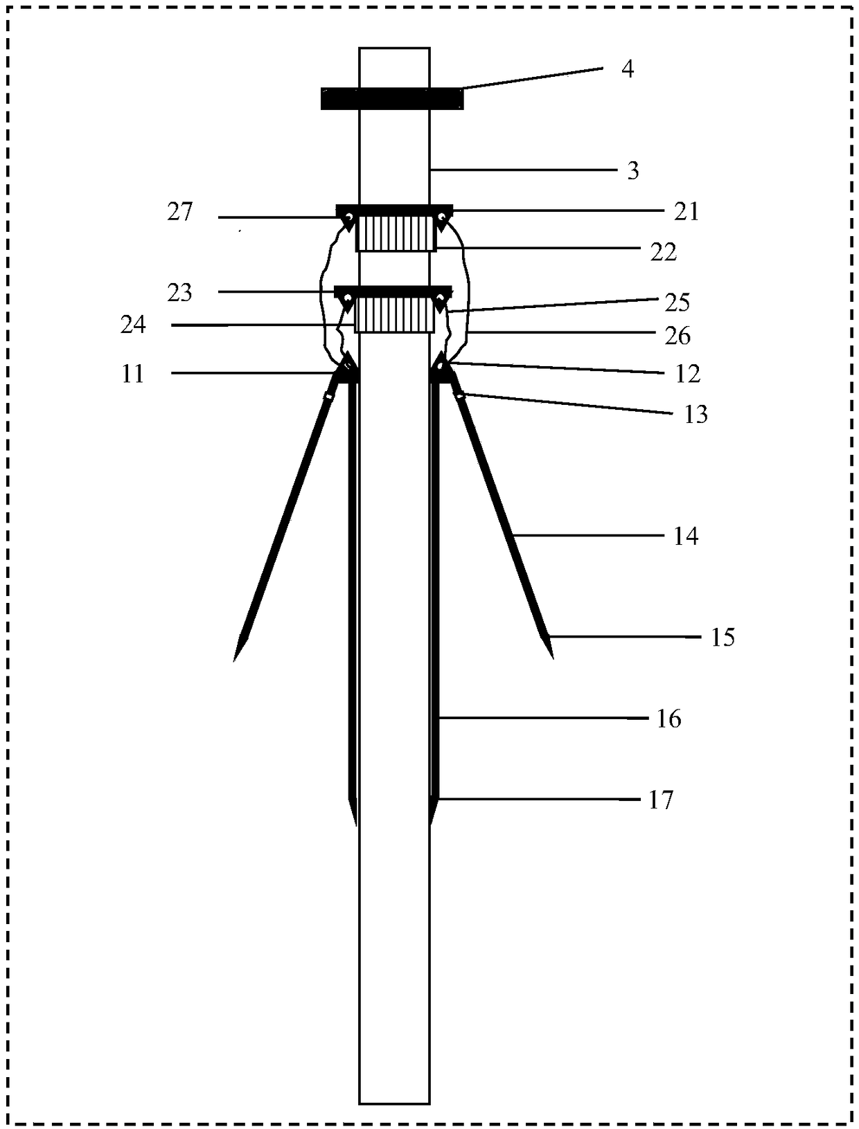
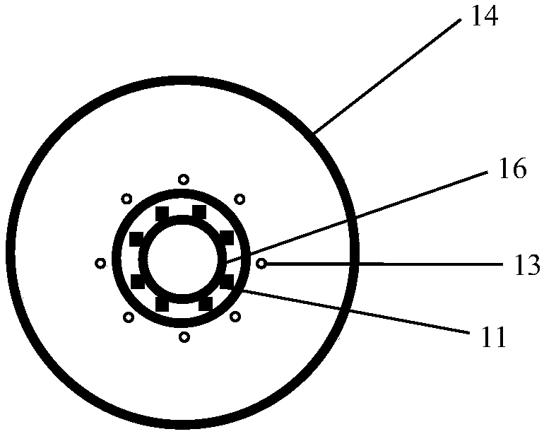
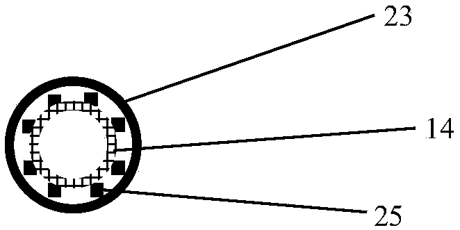
[0048] see figure 1 , figure 2 with image 3 , The deepwater drilling pipe support device while drilling includes a support assembly while drilling, a suspension assembly and a support plate 4 .

[0049] The support assembly while drilling is further divided into three parts, one part is the straight wall inner cylinder 16 in contact with the conduit, the other part is the inclined wall outer cylinder 14 with drainage holes 13 on the upper part, and the other part is the upper connection between the inner cylinder and the outer cylinder. top plate11. Most of the inner cylinder and the outer cylinder go deep into the soft soil below the seabed mud line to support the conduit and the weight attached to the conduit. The connecting top plate 11 is a thickened structure, one function is to connect the inner and outer cylinders, and the other function is to p...


PUM


Abstract

The invention provides a deep-water drilling guide pipe drilling supporting device and a drilling-in parameter design method. The device comprises a drilling supporting assembly, a suspension assembly and a supporting disc, wherein the drilling supporting assembly comprises an inner barrel, an outer barrel and a connecting top plate; the inner barrel sleeves a guide pipe and can freely slide along the guide pipe; the outer barrel is located outside the inner barrel and the diameter is gradually increased from the upper part to the lower part; and the outer barrel and the inner barrel are connected through the connecting top plate at the upper part. The upper end of the suspension assembly is fixed on the guide pipe and the lower end of the suspension assembly is hooked to the connecting top plate of the while-drilling supporting assembly, so that the while-drilling supporting assembly is suspended by the suspension assembly. The supporting disc is fixed nearby a guide pipe head and has the effect of suspending the guide pipe. The device is simple and convenient to operate and the technical problem of while-drilling supporting of the guide pipe can be solved. The drilling-in parameter design method provided by the invention is designed based on a basic principle of soil mechanics; meanwhile, requirements on site operation are sufficiently considered; and the design method is simple and convenient, a solving process is rapid and a calculation result is convenient for engineering application.

Description

technical field [0001] The invention relates to the field of marine deepwater drilling, in particular to a deepwater drilling conduit support device while drilling and a running parameter design method thereof. Background technique [0002] In the process of offshore deepwater drilling, after the conduit is lowered into place and connected to the underwater wellhead, blowout preventer and riser, it plays a structural support role. The conduit is generally installed at the design position below the seabed mud line by direct jetting or drilling first and then running and cementing. Only when there is no deflection during the running process can good running and supporting effects be guaranteed. With the continuous increase of water depth and the improvement of marine environmental protection requirements, the volume and weight of underwater blowout preventers tend to increase continuously. The underwater blowout preventer weighing hundreds of tons and the gravity of the suspe...

Claims


Application Information

Patent Timeline
Patent Type & Authority Patents(China)
IPC IPC(8): E21B15/00
CPCE21B15/00
Inventor 苏堪华刘继林万立夫李猛李清培石丽
Owner CHONGQING UNIVERSITY OF SCIENCE AND TECHNOLOGY
Why Eureka
Try Eureka