Rotation platform knee joint prosthesis

A technology of knee joint prosthesis and rotating platform, which is applied in the direction of knee joints, elbow joints, joint implants, etc., can solve problems such as over-rotation, and achieve the effect of over-rotation

Active Publication Date: 2017-10-24
北京安颂科技有限公司
View PDF9 Cites 1 Cited by
  • Summary
  • Abstract
  • Description
  • Claims
  • Application Information

AI Technical Summary

Problems solved by technology

[0007] The purpose of the present invention is to provide a rotating platform knee joint prosthesis to solve the technical problem of excessive rotation of the knee joint prosthesis in the prior art

Method used


Image

  • Rotation platform knee joint prosthesis
  • Rotation platform knee joint prosthesis
  • Rotation platform knee joint prosthesis

Examples


Embodiment 1

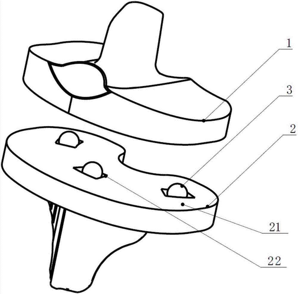
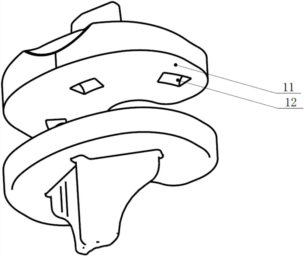
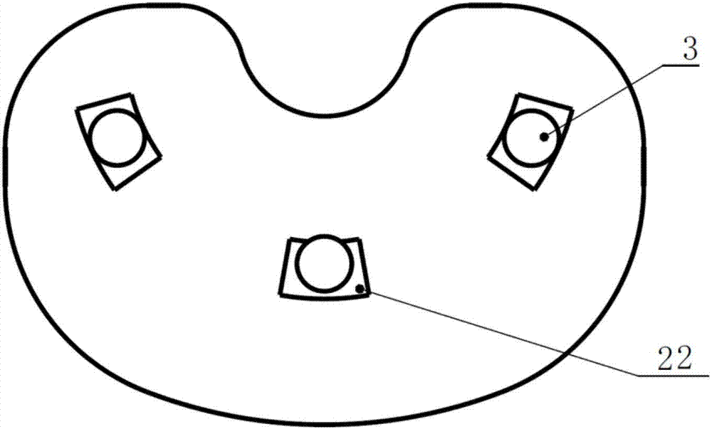
[0040] In the optional scheme of this embodiment, such as figure 1 with figure 2 As shown, a rotating platform knee prosthesis provided in this embodiment includes a tibial liner 1, a tibial tray 2, and a rolling element 3; the tibial liner 1 includes a liner base 11 and a liner groove 12, and the liner groove The groove 12 is arranged at the bottom of the cushion base 11; the tibial support 2 includes a support seat 21 and a support groove 22, and the support groove 22 is arranged on the top of the support seat 21; the liner base 11 and the support seat 21 are arranged oppositely; 3 is located in the cavity formed by the liner groove 12 and the bracket groove 22.

[0041] The existing knee joint prosthesis can realize the rotation of the knee joint during use, but because there is no limit design for the rotation angle, there will be unexpected over-rotation, which will lead to difficult or even impossible reset, affecting the use Effect.

[0042] In this embodiment, the ...

Embodiment 2

[0067] In an optional solution of this embodiment, a rotating platform knee joint prosthesis provided by this embodiment includes a tibial liner 1, a tibial support 2, and a rolling element 3; the tibial liner 1 includes a liner base 11 and a liner Groove 12, liner groove 12 is arranged on the bottom of liner base 11; tibial support 2 comprises support top seat 21 and support groove 22, support groove 22 is arranged on support top seat 21 top; liner base 11 and support top Seats 21 are arranged facing each other; rolling element 3 is located in the cavity formed by liner groove 12 and bracket groove 22 .

[0068] In this embodiment, the rotating platform knee prosthesis is designed as a separate assembly structure, including tibial liner 1, tibial support 2 and rolling element 3; the design concept of "thrust bearing" is adopted, and the rolling element 3 is located on the liner In the cavity formed by the groove 12 and the support groove 22, the rolling element 3 effectively ...


PUM


Abstract

The invention discloses a rotation platform knee joint prosthesis, and relates to the technical field of medical instruments. The rotation platform knee joint prosthesis comprises a tibia liner, a tibia holder and rolling elements. The tibia liner comprises a liner pedestal and liner grooves disposed at the bottom of the liner pedestal. The tibia holder comprises a holder top seat and holder grooves disposed at the top of the holder top seat. The liner pedestal and the holder top seat are oppositely arranged. The rolling elements are positioned in cavities formed by the liner grooves and the holder grooves. According to the rotation platform knee joint prosthesis, the rolling elements, the liner pedestal and the holder top seat can only rotate in the ranges of the cavities formed by the liner grooves and the holder grooves, limitation of rotation angles is achieved, the problem that a knee joint prosthesis may rotate excessively is solved, and the rotation platform knee joint prosthesis has promotion and application values.

Description

technical field [0001] The invention relates to the technical field of medical instruments, in particular to a rotating platform knee joint prosthesis. Background technique [0002] Artificial knee prosthesis, whose function is to restore the normal physiological functions of the human body, is implanted into the human body after knee replacement. [0003] In the normal flexion movement of the human knee joint, it will be accompanied by the relative rotation of the femur and the tibia, so after the replacement of the knee joint prosthesis, the prosthesis should also reproduce such a movement, so there is a fixed platform prosthesis on the market and rotating platform prostheses. The rotating platform prosthesis realizes the rotational movement of the knee joint through the relative movement between the tibial liner and the tibial tray, which is theoretically better than the fixed platform prosthesis. [0004] There are many structural forms of rotating platform prosthesis,...

Claims


Application Information

Patent Timeline
Patent Type & Authority Applications(China)
IPC IPC(8): A61F2/38
Inventor 贾海涛
Owner 北京安颂科技有限公司
Why Eureka
Try Eureka