
Test system and test method for simulating rapid changes in fluid temperature and/or pressure

A test system and fluid technology, which is used in the field of test systems for simulating rapid changes in temperature and/or pressure of aeroengine bleed air, and in the field of test systems for rapid changes in temperature and/or pressure, which can solve the problem of large number of equipment and heavy workload of equipment maintenance , large equipment size, etc.

Active Publication Date: 2020-07-21
COMAC +1
View PDF14 Cites 0 Cited by
  • Summary
  • Abstract
  • Description
  • Claims
  • Application Information

AI Technical Summary

Problems solved by technology

[0005] In the simulation of the instantaneous change of the rapid rise or fall of the temperature of the high and medium pressure air inlet caused by the rapid increase or decrease of the thrust of the conventional aeroengine, it is necessary to use components such as heaters, heat exchangers, and evaporators, but these components have their own characteristics. The effect of temperature response delay, causing the temperature change of the simulated gas to lag
[0006] During the pressure simulation test, the resistance in the test system changes, which affects the reliability of the pressure simulation and leads to the problem of slow pressure adjustment of the test system
[0007] In addition, there is a demand for cooling high-temperature gas in the test system, and conventional heat exchangers / coolers are used to reduce the temperature of the gas, which requires these components to have a larger heat transfer area and use a larger amount of cooling water. Large size of equipment brings problems such as large equipment size, large number of equipment and heavy equipment maintenance workload

Method used


Image

  • Test system and test method for simulating rapid changes in fluid temperature and/or pressure
  • Test system and test method for simulating rapid changes in fluid temperature and/or pressure
  • Test system and test method for simulating rapid changes in fluid temperature and/or pressure

Examples


Embodiment Construction

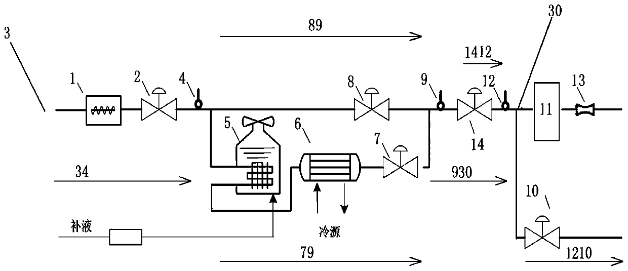
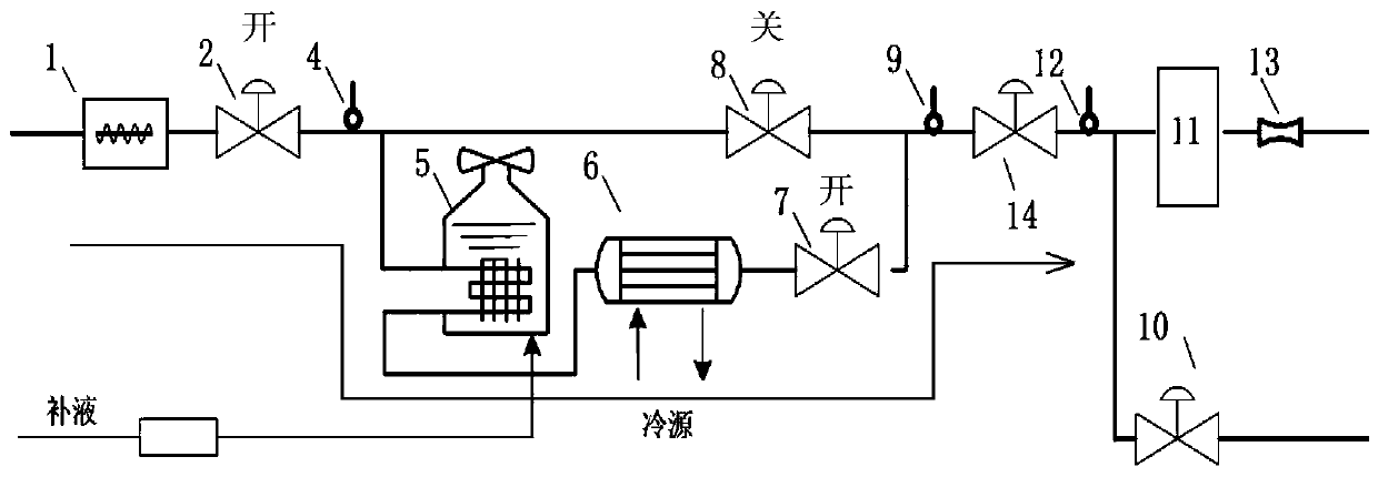
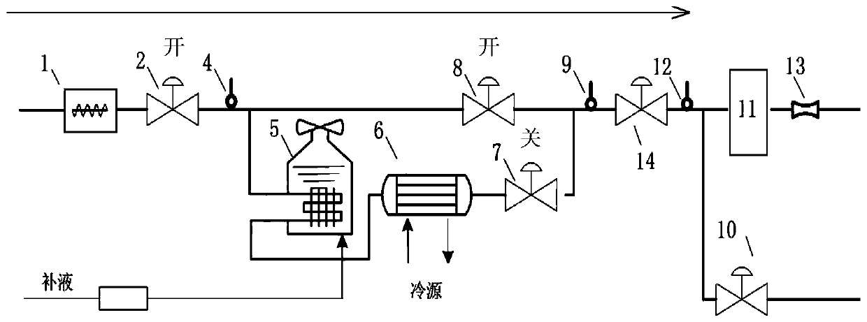
[0032] The present invention will be further described below in conjunction with the accompanying drawings and embodiments, so as to understand the inventive principle and beneficial technical effects of the present invention more clearly.

[0033] The reference numerals in the accompanying drawings of the description of the application correspond to the following structures in the embodiments:

[0034] 1: heater;

[0035] 2: The first pressure regulator of the high-temperature fast fine-tuning valve;

[0036] 4: The first temperature sensor;

[0037] 5: evaporator;

[0038] 6: heat exchanger;

[0039] 7: The second pressure regulator of the high-temperature fast fine-tuning valve;

[0040] 8: The third pressure regulator of the high-temperature fast fine-tuning valve;

[0041] 9: Second temperature sensor;

[0042] 10: The fourth pressure regulator of the quick pressure regulator;

[0043] 11: Test piece;

[0044] 12: pressure sensor;

[0045] 13: flow meter;

[004...


PUM


Abstract

The invention relates to a test system for simulating fluid temperature and / or pressure quick change. The test system comprises a heating flow path for regulating temperature; a temperature rising flow path which is communicated with the heating flow path; a cooling flow path of which the fluid is communicated with the heating flow path; and an output flow path of which the fluid is communicated with the temperature rising flow path and the cooling flow path. The heating flow path comprises an inlet end, a heater which is communicated with the inlet end, a first pressure regulating valve for regulating the fluid and a first temperature sensor for detecting the temperature. The cooling flow path fluid is connected with the output end of the heating flow path and the cooling flow path comprises an evaporator and a heat exchanger of which the fluid is mutually communicated and a second pressure regulating valve for regulating the fluid. The temperature rising flow path is connected with the output end of the heating flow path and comprises a third pressure regulating valve for regulating the fluid. The output flow path comprises a second temperature sensor which is communicated with the output end of the cooling flow path and the temperature rising flow path and an output end. According to the test system, the defects of high thermal inertial of temperature rising and cooling components, slow temperature change and variable system resistance can be overcome so as to improve the transient characteristic.

Description

technical field [0001] The present invention relates to aeronautical thermodynamic tests. Furthermore, the present invention relates to a test system and test method for simulating rapid changes in fluid temperature and / or pressure, in particular to a test system and test method for simulating rapid changes in aeroengine bleed air temperature and / or pressure. More specifically, the present invention relates to a test system and test method for simulating engine bleed air temperature and pressure changes during aircraft taxiing, take-off, climb, cruise, descent, etc. when conducting dynamic performance tests of environmental control system bleed air in a ground laboratory. Background technique [0002] The aviation thermodynamic test system is mainly used for the ground test of the aircraft environmental control system. By adjusting the pressure, flow, temperature and other parameters of the air supply from the air source, the user side (engine start-up bleed air, wing anti-d...

Claims


Application Information

Patent Timeline
Patent Type & Authority Patents(China)
IPC IPC(8): G01M99/00
CPCG01M99/002
Inventor 崔燚孙江平李德庆居世超刘鑫鑫戴铮段春闫佳妮张新太
Owner COMAC
Learn More