

Switching power supply
A switching power supply and switching technology, applied in the direction of electrical components, output power conversion devices, etc., can solve the problems of system device whistle, system cost increase, etc., and achieve the effects of improving EMI, suppressing ringing phenomenon, and avoiding LC oscillation
- Summary
- Abstract
- Description
- Claims
- Application Information
AI Technical Summary
Problems solved by technology
Method used
Image

Examples
Embodiment Construction
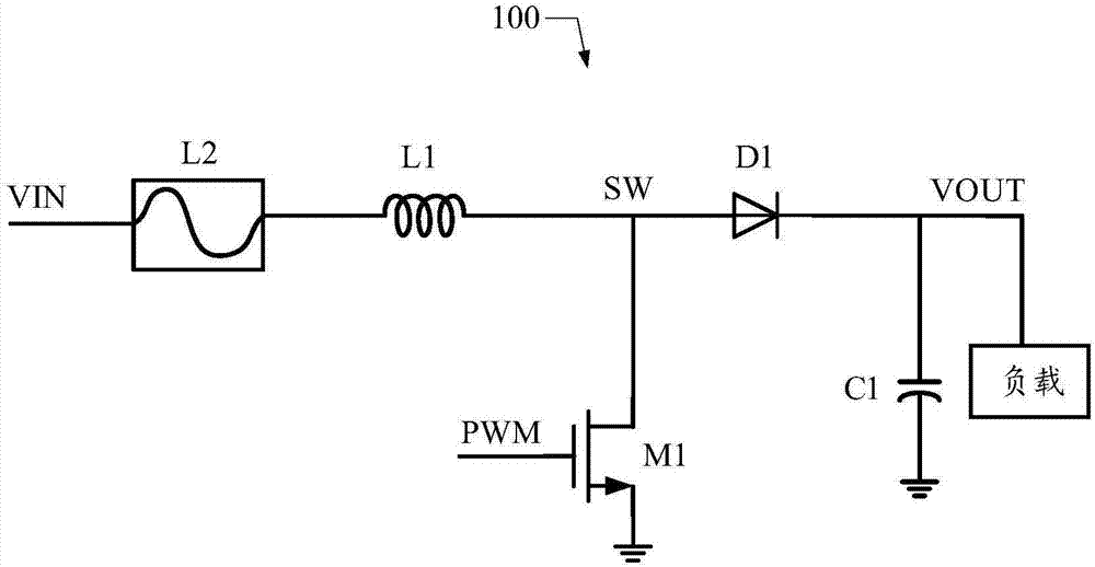
[0023] As mentioned in the background section, the method for suppressing the ringing phenomenon in the switching power supply in the prior art increases the system cost, and may also cause abnormalities such as howling of system components.
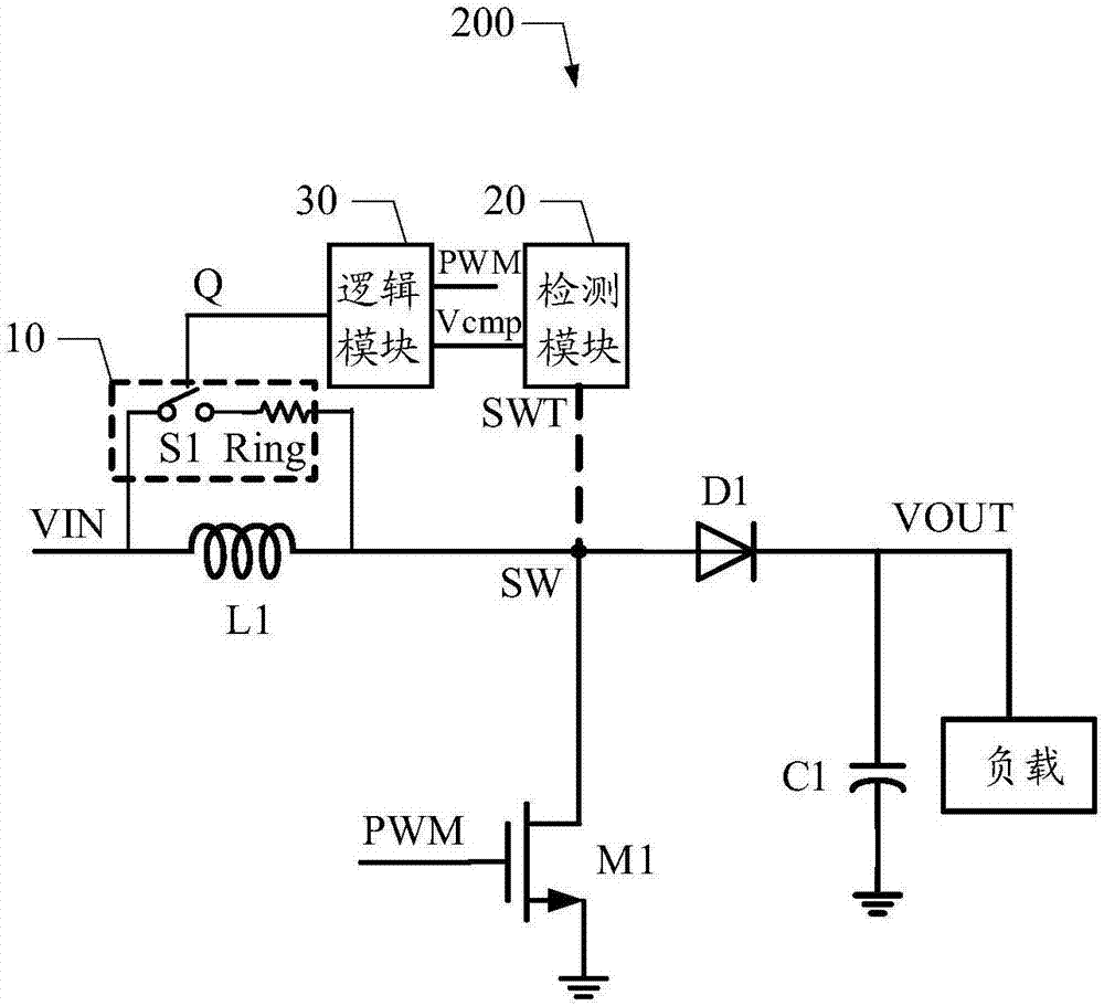
[0024] In view of the technical problems described above, an embodiment of the present invention proposes a switching power supply, which can suppress the ringing phenomenon and improve electromagnetic interference (EMI for short) of the switching power supply.
[0025] In order to make the above objects, features and beneficial effects of the present invention more comprehensible, specific embodiments of the present invention will be described in detail below in conjunction with the accompanying drawings.
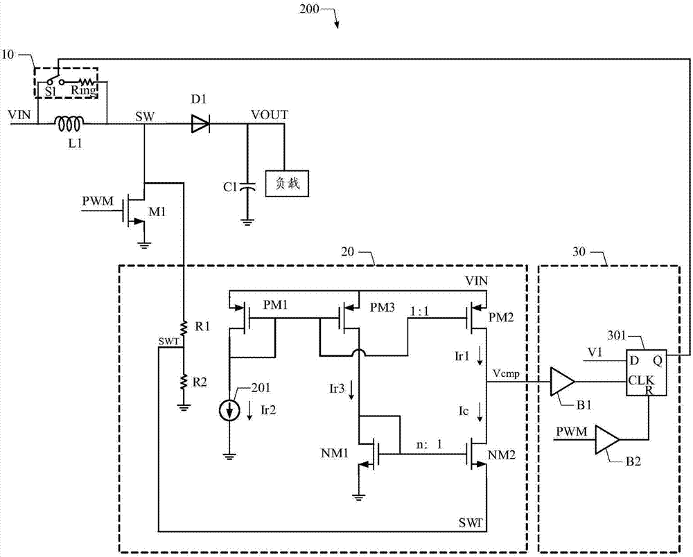
[0026] see figure 2 , the embodiment of the present invention discloses a switching power supply 200 . The solutions of the embodiments of the present invention can be applied to various types of switching power supplies and have u...
PUM
 Abstract
Description
Claims
Application Information