
Novel LED lamp

An LED lamp and a new type of technology, applied in the field of lighting, can solve the problems of inconvenient retraction and release of the power supply line of the wiring board, limited length of the power supply line, inducing electric shock accidents, etc., and achieve the effect of simple structure, convenient operation, and prevention of electric shock accidents.

Inactive Publication Date: 2017-11-03
DONGGUAN CITY GEDAMEI HARDWARE TOOLS CO LTD
View PDF0 Cites 0 Cited by
  • Summary
  • Abstract
  • Description
  • Claims
  • Application Information

AI Technical Summary

Problems solved by technology

[0002] LED lamps have gradually replaced the existing incandescent lamps and fluorescent lamps as lighting equipment for the new generation of weddings, evening parties, etc. The ideal power supply plug-in length has been reached by extending the connection through one or more terminal boards. However, the power supply line of the terminal board has a certain length, which is extremely inconvenient when retracting, and there are many plug-in points due to the connection of multiple terminal boards during the power supply process. Inadvertent human touch can easily induce electric shock accidents, posing a great safety hazard

Method used


Image

  • Novel LED lamp
  • Novel LED lamp
  • Novel LED lamp

Examples


Embodiment Construction

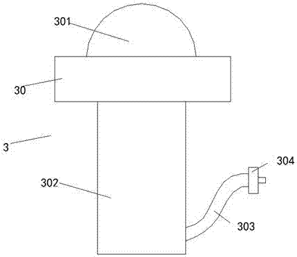
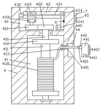
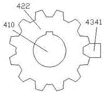
[0022] like Figure 1-Figure 6 As shown, a new type of LED lamp of the present invention includes a lamp part 3 and a power transmission box 4. A first cavity 41 is provided inside the power transmission box 4, and the power transmission on the top of the first cavity 41 The box 4 is provided with a second cavity 42, the inner top wall of the second cavity 42 is provided with a sliding joint groove 43, and the outer wall of the power transmission box 4 on the right side of the first cavity 41 is provided with an installation joint. Groove 44, a through groove 440 is provided between the attachment groove 44 and the first cavity 41, and an adapter shaft 410 that is elongated up and down is provided in the first cavity 41, and the adapter shaft The top of 410 penetrates the inner wall of the power transmission box 4 and penetrates into the second cavity 42 and is connected in operation. The adapter shaft 410 in the first cavity 41 is fixed with an adapter tube 411, the upper an...


PUM


Abstract

The invention discloses a new type of LED lamp, which includes a lamp part and a power transmission box. A first cavity is arranged inside the power transmission box, and a second cavity is arranged in the power transmission box on the top of the first cavity. The second cavity The inner top wall is provided with a sliding connection groove, and the outer wall of the power transmission box on the right side of the first cavity is provided with an installation groove, and there is a through groove between the installation groove and the first cavity, and the first cavity is provided with an upper and lower The elongated adapter shaft, the top of the adapter shaft penetrates the inner wall of the power transmission box and penetrates into the second cavity and is connected with the operation. The adapter shaft in the first cavity is fixed with an adapter tube. There are corresponding spacers on the upper and lower sides of the connecting pipe, cables are wound on the transfer pipe between the upper and lower sides of the spacers, and the first toothed wheel and the sliding groove are installed at the end of the top of the transfer shaft in the second cavity. There is a screw-shaped rod inside, and the left end surface of the screw-shaped rod is connected with the first electric rotating machine; the invention has simple structure, convenient operation, can automatically control the wire take-up and pay-off work, and improves work efficiency and safety.

Description

technical field [0001] The invention relates to the technical field of lighting, in particular to a novel LED lamp. Background technique [0002] LED lamps have gradually replaced the existing incandescent lamps and fluorescent lamps as lighting equipment for the new generation of weddings, evening parties, etc. The ideal power supply plug-in length has been reached by extending the connection through one or more terminal boards. However, the power supply line of the terminal board has a certain length, which is extremely inconvenient when retracting, and there are many plug-in points due to the connection of multiple terminal boards during the power supply process. Accidental human touch can easily induce electric shock accidents, and there is a great potential safety hazard. Contents of the invention [0003] The technical problem to be solved by the present invention is to provide a new type of LED lamp, which can solve the above-mentioned problems in the prior art. ...

Claims


Application Information

Patent Timeline
Patent Type & Authority Applications(China)
IPC IPC(8): F21S6/00F21V23/00F21V27/00F21V23/06F21V23/04F21Y115/10
CPCF21S6/00F21V23/002F21V23/04F21V23/0457F21V23/06F21V27/00F21Y2115/10
Inventor 方海超
Owner DONGGUAN CITY GEDAMEI HARDWARE TOOLS CO LTD
Learn More