
Fatigue test design method of aircraft engine suspension joint

A technology of aircraft engine and suspension joints, which is applied in the testing of mechanical components, testing of machine/structural components, measuring devices, etc., and can solve the problem of one-way actuator loading, distortion of test results, and given structure of aircraft lug joints. and other issues, to achieve the effect of clear engineering concept, clear analysis steps, and correct theoretical basis

Inactive Publication Date: 2017-11-07
XIAN AIRCRAFT DESIGN INST OF AVIATION IND OF CHINA
View PDF5 Cites 7 Cited by
  • Summary
  • Abstract
  • Description
  • Claims
  • Application Information

AI Technical Summary

Problems solved by technology

However, for the connection joint structure with a structure like the engine suspension joint and a complex stress state, the joint load and the direction of the action point are different under different load conditions, so it is impossible to load through the one-way actuator, and the test implementation often requires a lot of time. One actuator is used for collaborative loading, and the test implementation often requires multiple actuators for coordinated loading. For the above-mentioned specific lug joint structure, considering the scale of the test piece and the test cost, it is impossible to carry out the test according to the large component level support method.
In order to simplify the test, the relevant designers decomposed the joint structure and simplified the fatigue test. However, due to the difficulty of simulating the real aircraft due to the support boundary and load state, the test results were distorted
[0005] In the prior art, most of the studies on the formulation of aircraft structural fatigue test programs are based on the consistency of the stress state of the test piece, the design of the transition section and support section of the test piece, the simulation of the test piece constraint, and the optimization of the test load. Theoretical elaboration failed to provide a practical fatigue test design method for the aircraft lug joint structure itself in terms of its stress and load characteristics

Method used


Image

  • Fatigue test design method of aircraft engine suspension joint
  • Fatigue test design method of aircraft engine suspension joint
  • Fatigue test design method of aircraft engine suspension joint

Examples


Embodiment Construction

[0030] In order to make the objectives, technical solutions and advantages of the present invention clearer, the technical solutions in the embodiments of the present invention will be described in more detail below in conjunction with the drawings in the embodiments of the present invention. In the drawings, the same or similar reference numerals denote the same or similar elements or elements having the same or similar functions throughout. The described embodiments are some, but not all, embodiments of the invention. The embodiments described below by referring to the figures are exemplary and are intended to explain the present invention and should not be construed as limiting the present invention. Based on the embodiments of the present invention, all other embodiments obtained by persons of ordinary skill in the art without creative efforts fall within the protection scope of the present invention. Embodiments of the present invention will be described in detail below ...


PUM


Abstract

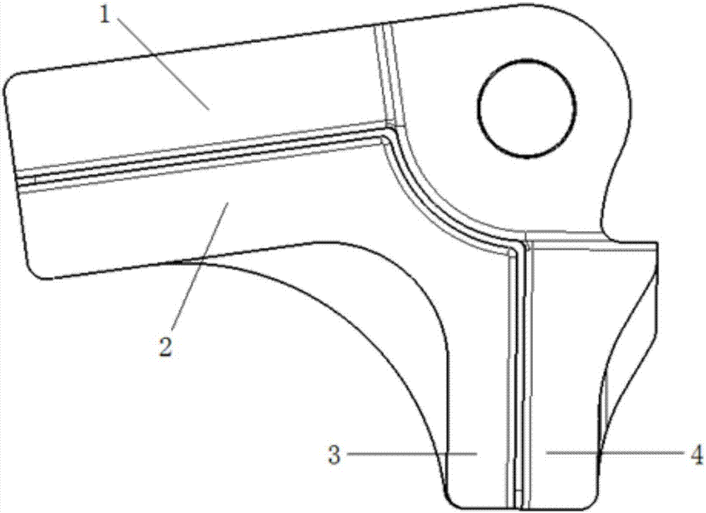
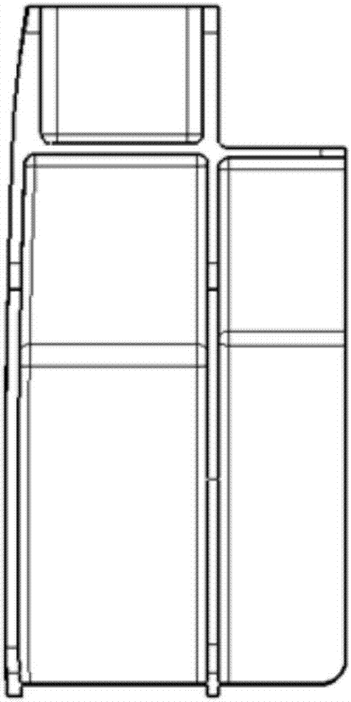
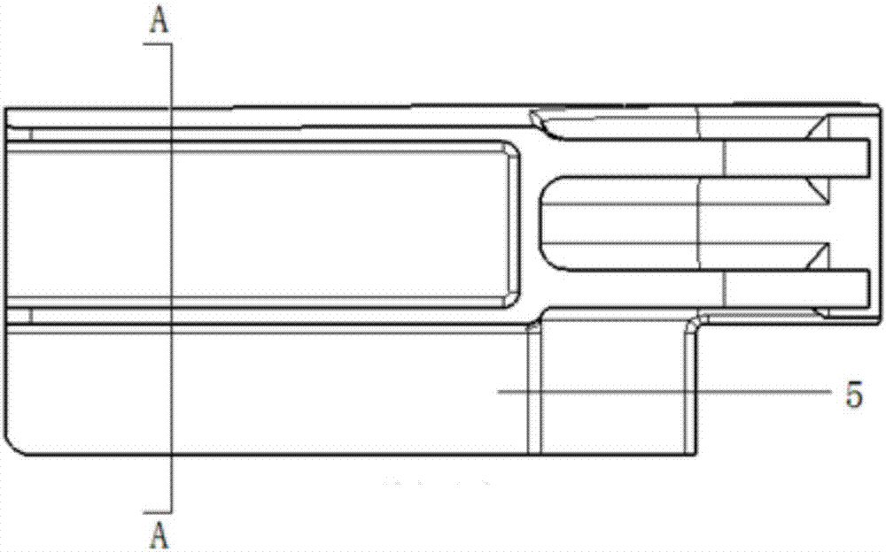
The invention discloses a fatigue test design method of an aircraft engine suspension joint and belongs to the technical field of aircraft structural part fatigue tests. The method comprises the following steps of: firstly, obtaining suspension joint load under respective load conditions; secondly, distributing the suspension joint load according to a rigidity ratio of rims on the suspension joint to simplify the structural form of a test piece; during a test, loading the suspension joint by using a two-way independent loading way; monitoring the state of the to-be-checked part of the suspension joint to acquire experimental data; and finally, comparing the acquired experimental data and a theoretical analysis result and correcting a calculation model and a calculation result. The fatigue test design method simplifies the test piece according to a law of load distribution according to stiffness, monitors the test piece and corrects the calculation model and the calculation result by using a smart coating and a strain gauge, achieves a test checking and monitoring purpose, and simplifies a test scale and reduces test cost.

Description

technical field [0001] The invention belongs to the technical field of fatigue tests of aircraft structural parts, and in particular relates to a fatigue test design method for hanger joints of aircraft engines. Background technique [0002] The aircraft engine suspension joint is used to suspend the engine, which is subjected to a relatively large force and needs to be subjected to a fatigue test. Usually, the aircraft engine suspension joint is a lug joint. [0003] The core of the aircraft lug joint structure fatigue test is usually reflected in the planning and formulation of the test program. When formulating the test plan, the designer must do comprehensive theoretical analysis and finite element calculation to ensure that the test plan can not only simulate the real loading state of the test piece, but also take into account the implementation and monitoring of the test. [0004] For the one-way connection joint structure, the position and direction of the load actio...

Claims


Application Information

Patent Timeline
IPC IPC(8): G01M13/00
CPCG01M13/00
Inventor 闵强王亚芳王新波宁宇
Owner XIAN AIRCRAFT DESIGN INST OF AVIATION IND OF CHINA
Learn More