Improved new energy automobile charging equipment

A technology of new energy vehicles and charging equipment, applied in electric vehicle charging technology, charging stations, electric vehicles, etc., can solve user safety accidents, time-consuming and labor-intensive, casualties and other problems, to prevent electric shock accidents, reduce manufacturing costs, The effect of reducing equipment investment

Inactive Publication Date: 2017-11-10
YICHANG HUIYIXING NEW ENERGY TECH CO LTD
View PDF0 Cites 3 Cited by
  • Summary
  • Abstract
  • Description
  • Claims
  • Application Information

AI Technical Summary

Problems solved by technology

Electric vehicles are inseparable from charging piles, but in the process of charging electric vehicles with existing charging piles, they are all manually plugged and unplugged by personnel. During the plugging and unplugging process, the charging head is prone to arc due to the influence of voltage, and the generation of arc is easy to cause damage to the electric vehicle. The electric shock of the user has cer

Method used


Image

  • Improved new energy automobile charging equipment
  • Improved new energy automobile charging equipment
  • Improved new energy automobile charging equipment

Examples


Embodiment Construction

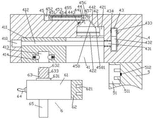
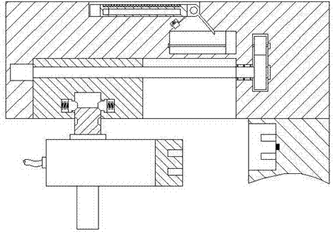
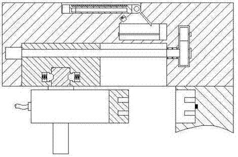
[0027] Such as Figure 1-Figure 7 As shown, an improved new energy vehicle charging device of the present invention includes a power supply part 5, a propulsion part 4 fixedly connected to the top of the power supply part 5 and extending to the left, and a charging gun 6. The power supply part 5 An insertion slot 51 is provided in the left end surface, and power supply pins 511 arranged symmetrically up and down are arranged on the inner wall on the right side of the insertion slot 51, and the insertion slot 51 between the two groups of power supply pins 511 is on the right side. A sensor 512 on the side inner wall, a storage groove 45 is provided in the top end surface of the propulsion part 4, a sliding groove 41 is provided in the bottom end surface of the left side of the propulsion part 4, and the propulsion part 4 on the upper right side of the sliding groove 41 A sliding chamber 42 is provided inside, and a transmission chamber 43 is provided in the sliding chamber 42 a...


PUM


Abstract

The invention discloses improved new energy automobile charging equipment. The improved new energy automobile charging equipment comprises a power supply part, a pushing part and a charging gun, wherein the pushing part is fixedly connected with the top of the power supply part and arranged to extend to the left side; an inserting groove is formed in the end surface of the left side of the power supply part; power supply inserting pins, which are symmetrically arranged in an up-and-down direction, are arranged on the inner wall of the right side of the inserting groove; a sensor is arranged in a position, between the two groups of power supply inserting pins, on the inner wall of the right side of the inserting groove; a storage groove is formed in the end surface of the top of the pushing part; a sliding groove is formed in the end surface of the bottom of the left side of the pushing part; a sliding chamber is formed in a position, above the right side of the sliding groove, in the pushing part; a transmission chamber is formed in a position, on the right sides of the sliding chamber and the sliding groove, in the pushing part; a first gear is arranged on the downside within the transmission chamber; the top of the first gear is in engaged connection with a second gear; a first rotating shaft arranged to extend from left to right is fixedly arranged on the first gear; and a second rotating shaft arranged to extend from left to right is fixedly arranged on the second gear. The improved new energy automobile charging equipment has the advantages that the structure is simple, manual inserting can be replaced, the working efficiency can be enhanced, the inserting stability can be improved, the safety is high and an indicating function is achieved.

Description

technical field [0001] The invention relates to the technical field of new energy vehicle charging, and relates to an improved charging device for new energy vehicles. Background technique [0002] An electric vehicle refers to a vehicle powered by an on-board power supply and driven by a motor to drive the wheels. Compared with gasoline engine vehicles, electric vehicles have less impact on the environment and can replace the use of non-renewable energy gasoline. Therefore, the prospect of electric vehicles is widely optimistic, and it also meets the requirements of new energy strategies. Electric vehicles are inseparable from charging piles, but in the process of charging electric vehicles with existing charging piles, they are all manually plugged and unplugged by personnel. During the plugging and unplugging process, the charging head is prone to arc due to the influence of voltage, and the generation of arc is easy to cause damage to the electric vehicle. The electric ...

Claims


Application Information

Patent Timeline
IPC IPC(8): B60L11/18H01R12/00
CPCB60L53/31H01R12/00Y02T10/70Y02T10/7072Y02T90/12
Inventor 鲍佳佳
Owner YICHANG HUIYIXING NEW ENERGY TECH CO LTD
Why Eureka
Try Eureka