Drawer type power control cabinet device convenient to maintain

A power control cabinet and drawer-type technology, which is applied in the field of power, can solve the problems of unfavorable control cabinet maintenance, complex mechanical and electronic structures, and the inability to flexibly realize the releasable manual removal of drawer components.

Active Publication Date: 2017-11-10
徐州新电高科电气有限公司
View PDF4 Cites 3 Cited by
  • Summary
  • Abstract
  • Description
  • Claims
  • Application Information

AI Technical Summary

Problems solved by technology

In order to facilitate maintenance, power control cabinets usually have drawers for pushing and pulling to maintain the power equipment inside. The existing drawer-type control cabinet devices often need to be manually pulled out, which causes inconvenience to use.
However, the use of power to realize the pulling movement cannot flexibly realize the releasable manual removal of the drawer assembly, which causes disadvantages to the maintenance work of the control cabinet.
However, if you want to realize this kind of method that can not only push and pull by power, but also facilitate the manual removal of the drawer for maintenance, you need a more complicated mechanical and electronic structure, which will have a negative impact on maintenance and equipment costs.

Method used


Image

  • Drawer type power control cabinet device convenient to maintain
  • Drawer type power control cabinet device convenient to maintain
  • Drawer type power control cabinet device convenient to maintain

Examples


Embodiment Construction

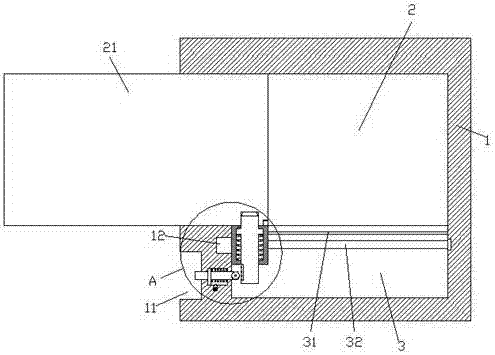
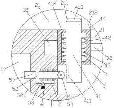
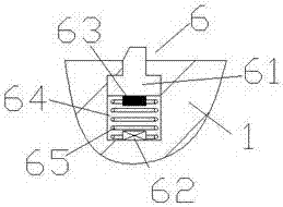
[0016] Such as Figure 1-Figure 5 As shown, a drawer-type power control cabinet device that is easy to maintain in the present invention includes a cabinet body 1, and an accommodating chamber 2 is provided inside the cabinet body 1, and the cabinet body 1 below the accommodating chamber 2 is provided with A push slot 3, a drawer assembly 21 is provided inside the accommodation cavity 2, a pressing area 11 is provided on the outer wall of the cabinet body 1 on the left side of the push slot 3, and a space between the pressing area 11 and the push slot 3 The cabinet body 1 is provided with a pressing chamber 5 and a clamping device 6 arranged below the pressing chamber 5. The pressing chamber 5 is provided with a pressing rod 51 extending to the left and right sides. The pressing rod 51 is left The side extension section runs through the left side wall of the cabinet body 1 and extends into the pressing area 11, and the right extension section of the pressing rod 51 passes thro...


PUM


Abstract

The invention discloses a drawer type power control cabinet device convenient to maintain. The device comprises a cabinet body in which an accommodating cavity is arranged, wherein a pushing groove is arranged in the cabinet below the accommodating cavity, a drawer component is arranged in the accommodating cavity, a pressing area is arranged on the outer wall of the cabinet on the left of the pushing groove, a pressing cavity is arranged in the cabinet between the pressing area and the pushing groove and a clamp connection device is arranged below the pressing cavity, a pressing rod extending to left and right sides is arranged in the pressing cavity, and the extension section on the left of the pressing rod stretches into the pressing area after penetrating through the left side wall of the cabinet body. According to the device provided by the invention, automatic inward and outward moving is achieved, and the drawer component is independently dismounted, so that different overhauling requirements can be met, overhauling of staffs is facilitated, overhauling efficiency is improved, and the whole structure is stable in operation.

Description

technical field [0001] The invention relates to the technical field of electric power, in particular to a drawer type power control cabinet device which is convenient for maintenance. Background technique [0002] The power control cabinet is a common component in the field of power switch control. The power control cabinet is used to install various switches, controllers and other power equipment for power control. In order to facilitate maintenance, the power control cabinet usually has a drawer for pushing and pulling to maintain the power equipment inside. The existing drawer type control cabinet device often needs to be manually pulled when pulling, which causes inconvenience to use. However, the use of power to realize the pulling movement cannot flexibly realize the releasable manual removal of the drawer assembly, thereby causing disadvantages to the maintenance work of the control cabinet. However, if it is desired to realize such a method that can not only push a...

Claims


Application Information

Patent Timeline
Patent Type & Authority Applications(China)
IPC IPC(8): H02B11/173
CPCH02B11/173
Inventor 朱亚伟
Owner 徐州新电高科电气有限公司
Why Eureka
Try Eureka