
Apparatus and method for vertical and lateral fatigue test of longitudinal leaf spring

A technology of fatigue experiment and leaf spring, which is applied in the direction of measuring device, machine/structural component test, mechanical component test, etc., can solve the problems of fatigue experiment reliability and authenticity to be improved, no installation, etc., so as to improve reliability and authenticity, improved reliability, high authenticity effect

Active Publication Date: 2020-04-10
ZHUZHOU TIMES NEW MATERIALS TECH
View PDF8 Cites 0 Cited by
  • Summary
  • Abstract
  • Description
  • Claims
  • Application Information

AI Technical Summary

Problems solved by technology

In this plan, the test tooling for three-way loading of the leaf spring is given, but it is not installed according to the actual installation structure of the leaf spring on the car. Are not the same
[0009] Thus, in the prior art, there is no composite loading device designed according to the actual installation method, size and loading motion deformation characteristics of the vertical leaf spring on the automobile, and the reliability of the fatigue experiment of the composite direction loading of the leaf spring and authenticity needs to be improved

Method used


Image

  • Apparatus and method for vertical and lateral fatigue test of longitudinal leaf spring
  • Apparatus and method for vertical and lateral fatigue test of longitudinal leaf spring
  • Apparatus and method for vertical and lateral fatigue test of longitudinal leaf spring

Examples


Embodiment Construction

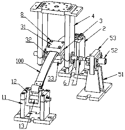
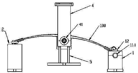
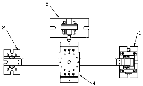
[0034] Combine below Figure 1 to Figure 4 Embodiments of the present invention are described in detail.

[0035] The longitudinal vertical fatigue test device of the plate spring includes the lifting lug bearing seat 1, the lifting lug fixing seat 2 aligned with the lifting lug bearing seat 1, and the middle clamping seat 3 clamped and fixed on the middle section of the leaf spring 100, along the vertical The vertical reinforcement frame 4 arranged in the direction and connected with the vertical loading device and the lateral reinforcement seat 5 arranged in the side direction and connected with the lateral loading device are characterized in that one end of the leaf spring 100 is arranged in the longitudinal direction. It is swingably mounted on the lifting lug bearing seat 1, and the other end of the lifting lug is fixed on the lifting lug fixing seat 2. The vertical reinforcement frame 4 is in the shape of a door frame, and straddles the middle clamping seat 3 in the late...


PUM


Abstract

Provided are a device and method for a vertical and lateral fatigue test of a spring of a vertical plate. The device for the vertical and lateral fatigue test of the spring of the vertical plate comprises a lifting lug bearing base, a lifting lug fixing base aligned to the lifting lug bearing base, a middle clamping base clamped and fixed at the middle section of the spring of the vertical plate, a vertical loading frame disposed vertically and connected with a vertical loading device and a lateral loading base arranged laterally and connected with a lateral loading device, and is characterized in that a lifting lug arranged vertically at one end of the spring of the vertical plate is mounted on the lifting lug bearing base in a swinging mode, and a lifting lug arranged vertically at the other end of the spring of the vertical plate is fixed on the lifting lug fixing base; the vertical loading frame is in a door frame shape, and is arranged across the middle clamping base in a lateral direction and rotatably connected with the middle clamping base through a stressed shaft arranged in the lateral direction; the stressed shaft is fixed on the middle clamping base, and the lateral loading base is located at the side edge of the spring of the vertical plate and connected with one end of the stressed shaft through a joint bearing, arranged in the lateral direction, at the end of a ball rod. According to the device and method for the vertical and lateral fatigue test of the spring of the vertical plate, the vertical and lateral fatigue life of the spring of the vertical plate is detected, and the reliability and the authenticity of the fatigue test, which loads in a composite direction, of the spring of the vertical plate are improved.

Description

technical field [0001] The invention relates to a vertical and longitudinal fatigue test device and method for a vertical plate spring, which is used for performing vertical and longitudinal fatigue tests on a vertical plate spring. Background technique [0002] The leaf spring is generally fixed on the axle with two or two U-shaped bolts, and the bushings are pressed into the lug holes at both ends of the spring. The right hanging lug is connected with the front bracket by a leaf spring pin to form a fixed fulcrum; the left hanging lug is connected with the hanging lug which is hinged on the hanging lug bracket and can swing freely through the front leaf spring lifting lug pin, thus ensuring When the spring deforms, the distance between the centerlines of the two lifting lugs may change. [0003] With the improvement of automobile comfort and energy saving and environmental protection requirements, the requirements for lightweight automobiles are getting higher and higher....

Claims


Application Information

Patent Timeline
Patent Type & Authority Patents(China)
IPC IPC(8): G01M13/00
CPCG01M13/00
Inventor 王叶青林达文李建林刘波王进李心彭立群左斌刘晓倩
Owner ZHUZHOU TIMES NEW MATERIALS TECH
Learn More