Amusement apparatus and method

a technology of amusement equipment and a method, applied in the field of mechanical and visual motion simulation aspects, can solve the problems of unsatisfactory visual effect and unrealistic feeling of outside observation, and achieve the effect of enhancing the illusion of real fligh

Inactive Publication Date: 2005-01-20
LI MING +3
View PDF10 Cites 43 Cited by
  • Summary
  • Abstract
  • Description
  • Claims
  • Application Information

AI Technical Summary

Benefits of technology

[0003] Our present invention is aimed to solve the problem where this type of simulator, which would reside in an amusement park or similar entertainment venue, that does not provide tourists with immersed enough experience. The present invention provides a motion simulator for entertainment purposes that can move tourists and produces a convincing illusion of actual flight in a surrounding scene. The purpose of the present invention is to provide a new amusement motion simulator apparatus and method that is combined with projecting image, which enables the tourist to feel like really flying in the sky.
[0015] The present invention can project a 2D or 3D image on the screen by one or two projectors respectively. The revolving platform and swaying seats move synchronously with the images to enhance the realistic effects. The present invention has the following advantages over the previous similar devices:
[0017] b. It is more convenient and safe for the passengers to go into and out of the machine.
[0018] c. Passengers are just before the display screen, which enable them to have a wider view and will not impede each other's lines of vision.
[0019] d. Passengers seating in passenger seats are suspended in the air combining the pitching motion of the seats, which enhance the illusion of real flight.

Problems solved by technology

Furthermore, tourists watch a movie by sitting in the motionless passenger seats arranged in longitude with space in relation to each other, which gives an unrealistic feeling of outside observation.
Since the goal of this type of theater is to bring extreme realism, the visual effect is not quite ideal due to the limitations of the above reasons.

Method used


Image

  • Amusement apparatus and method
  • Amusement apparatus and method
  • Amusement apparatus and method

Examples


Embodiment Construction

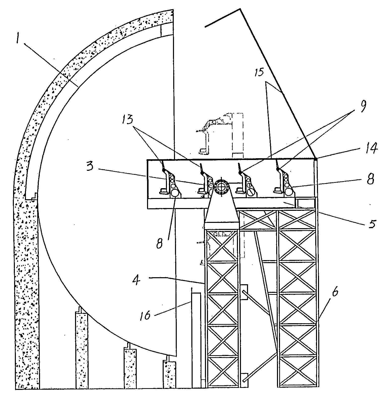
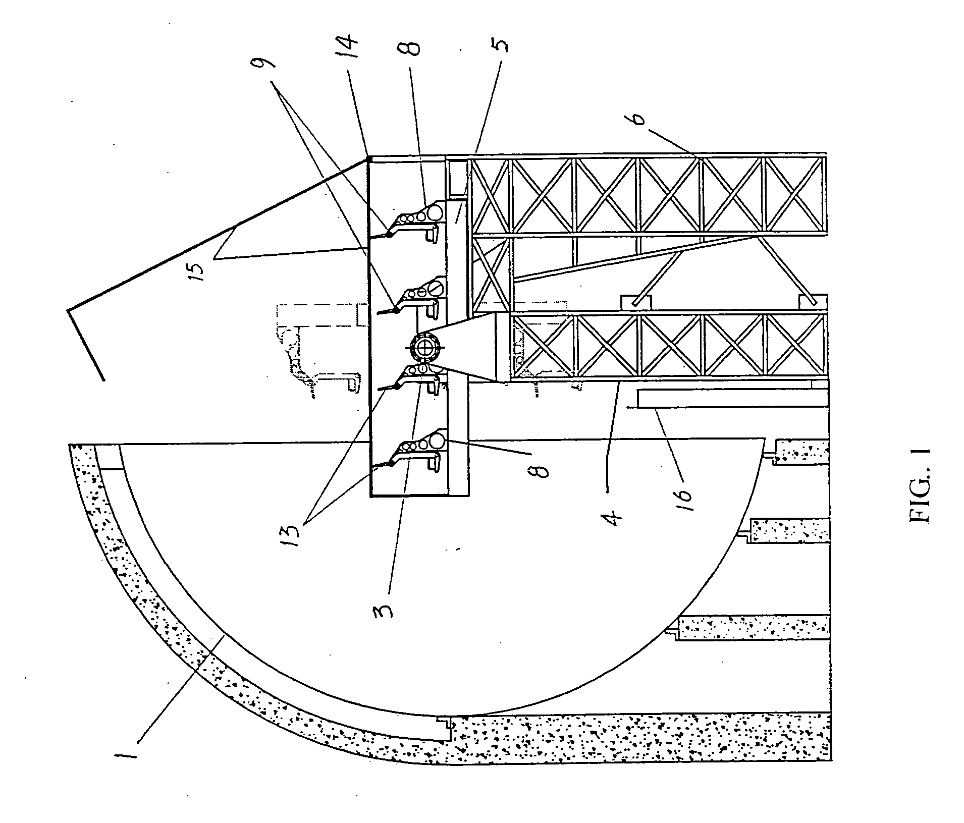
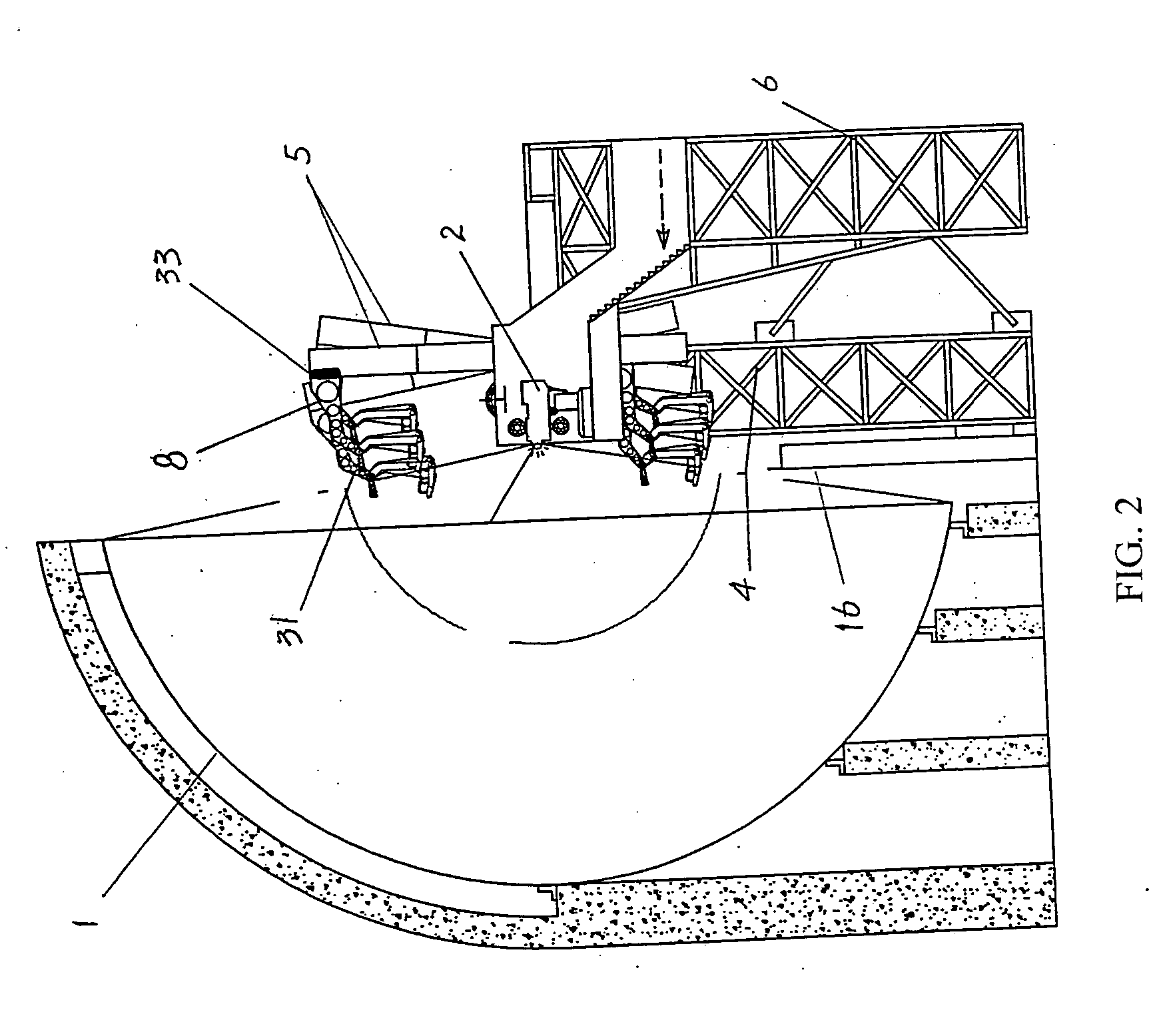
[0029] Referring to FIGS. 1, 2 and 3. They are drawings of a preferred embodiment of the present invention, comprising of the hemisphere screen 1 or other forms of screens and display assembly positioned at the center of the hemisphere screen. Platform 5 is positioned on the support stanchion 4 and linked with platform rotating shaft 3. Hemisphere screen 1 is located just in front of platform 5. There are one or two projectors positioned inside the machine room at the center of the hemisphere screen. There is a hollow space in the middle part of the platform 5 that enables the platform to be kept away from the machine room at any position and ensures there is enough safety space between the passenger seats and the equipment room. The Machine room is sustained by the tower 6 and is completely independent from the platform 5. The Route way to the machine room is inside the structure of tower 6 connecting to outside. Passenger seats 7 arranged in longitudinally and transverse direction...


PUM


Abstract

An amusement simulation apparatus and method is disclosed. The simulation apparatus includes screen, projector, rotating platform carrying passenger, rotating shaft and aligned passenger seats round the machine room positioned on the platform and hanging by the suspending structure. When the platform is in upright position, passengers seating in the passenger seats face the screen positioned in front and view the image (2D or 3D) projected on the screen. The passengers are almost in the same vertical plane but in up and down relation. The blocking plate divided the passengers in different rows. The platform and the passenger seats can both pivot upon their shaft. Passenger seats in the left and right columns can rotate round the longitudinal yawing shaft to achieve better viewing effect. Pivoting movement of the passenger seat, combining the special effect of wind blasting, simulates the flying experience vividly. The simulation apparatus is suitable for use in an amusement park or theme park, providing tourists with interesting and life like flying experience.

Description

FIELD OF THE INVENTION [0001] This invention is made up of mechanical and visual motion simulation aspects. In particular this invention combines a motion simulator with projected visual images in a custom method described below. BACKGROUND OF THE INVENTION [0002] Previously, other spherical theaters worked like this: The films are projected on a hemispherical screen that provides tourists with a new visual experience by projecting film with film projector at the center of the hemisphere screen, but only a planar image can be projected as only one projector is adopted. Furthermore, tourists watch a movie by sitting in the motionless passenger seats arranged in longitude with space in relation to each other, which gives an unrealistic feeling of outside observation. Since the goal of this type of theater is to bring extreme realism, the visual effect is not quite ideal due to the limitations of the above reasons. SUMMARY OF THE INVENTION [0003] Our present invention is aimed to solve...

Claims


Application Information

Patent Timeline
Patent Type & Authority Applications(United States)
IPC IPC(8): A63G31/16
CPCA63G31/16
Inventor LI, MINGRONG, ZHIGANGGAO, JINGYILIU, DAOQIANG
Owner LI MING
Why Eureka
Try Eureka