Tool assembly

A technology of knives and tool holders, applied in the direction of manufacturing tools, stone processing tools, work accessories, etc., can solve the problems of low cutting efficiency, achieve the effects of improving work efficiency, preventing slippage, and strengthening relative fixing force

Inactive Publication Date: 2017-11-21
包光华
View PDF0 Cites 1 Cited by
  • Summary
  • Abstract
  • Description
  • Claims
  • Application Information

AI Technical Summary

Problems solved by technology

[0003] In order to solve the problem of low cutting efficiency in the prior art, the present invention provides a novel cutter combination

Method used


Image

  • Tool assembly
  • Tool assembly

Examples


Embodiment Construction

[0014] The present invention will be further explained in detail below in conjunction with the accompanying drawings and specific embodiments, but it should be understood that the protection scope of the present invention is not limited by the specific embodiments.

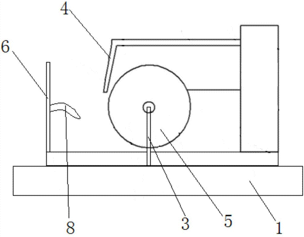
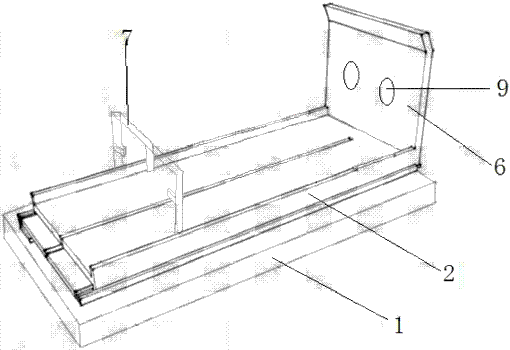
[0015] like figure 1 , 2 As shown, the cutter 5 combination in the present invention includes a base 1, a slide plate 2 connected to the base 1 by slide rails, a cutter 5 frame 3 erected on the base 1, and water nozzles 4 placed on both sides of the cutter 5, rock The cutting process produces a large amount of heat, which is easy to damage the blade. The water flow nozzle 4 is placed on the side of the cutter 5 blade, and the sprayed water flows into the blade to cool down. Cutter 5 frame 3 comprises a rotating shaft across slide plate 2, and rotating shaft is parallel to sliding plate 2, and the rotating shaft is provided with a plurality of draw-in slots for connecting cutter 5, and cutter 5 is connected on the...


PUM


Abstract

The invention relates to a knife combination, which comprises a base, a sliding plate slidably connected to the base, a tool holder erected on the base and water spray nozzles placed on both sides of the cutter. Sliding board is provided, and described cutter is provided with several, and several cutters are parallel to each other, and one end of described sliding board is vertically fixedly connected with the baffle plate that is used for preventing water from splashing on staff's clothes, and described baffle board is provided with two parallel holes, so Said hole is connected with a waterproof sleeve. The present invention is equipped with a plurality of knives at the same time, and the products to be processed are cut at a plurality of stations at the same time, and a plurality of flakes or columns are cut out at one time, which greatly improves the work efficiency.

Description

technical field [0001] The invention relates to a cutter combination, in particular to a cutter combination capable of performing multi-station cutting at the same time. Background technique [0002] Existing rock cutting tools usually use manual force to fix the rock on the slide and push the rock to the tool, and only one part can be cut at a time. Sometimes the rock needs to be cut into multiple columns of the same size during the experiment. At this time, the rock needs to be cut into flakes and then cut into multiple columns in turn. The disadvantages of the existing device will appear, the cutting efficiency is low, and manual fixing will easily lead to the deviation of the cutting direction caused by the movement of the rock during the cutting process. . Contents of the invention [0003] In order to solve the problem of low cutting efficiency in the prior art, the present invention provides a novel cutter combination. [0004] In order to solve the above-mentione...

Claims


Application Information

Patent Timeline
Patent Type & Authority Applications(China)
IPC IPC(8): B28D1/24B28D7/04B28D7/00B28D7/02
CPCB28D1/24B28D7/00B28D7/02B28D7/04
Inventor 包光华
Owner 包光华
Why Eureka
Try Eureka