Beamforming using an antenna array

An antenna array and beamforming technology, applied in antennas, modular arrays, antenna components, etc., to solve problems such as inappropriate antenna arrays and reduced total output power

Active Publication Date: 2017-12-01
TELEFON AB LM ERICSSON (PUBL)
View PDF7 Cites 2 Cited by
  • Summary
  • Abstract
  • Description
  • Claims
  • Application Information

AI Technical Summary

Problems solved by technology

However, when signals are to be transmitted over a larger area (such as control plane transmissions), such antenna arrays are less suitable if conventional techniques are used to form wider transmit beams
Conventional techniques apply amplitude tapering, which results in many power amplifiers in the radio chain being more or less unused, thus reducing the total output power

Method used


Image

  • Beamforming using an antenna array
  • Beamforming using an antenna array
  • Beamforming using an antenna array

Examples


Embodiment Construction

[0030] The inventive concepts will now be described more fully hereinafter with reference to the accompanying drawings, in which specific embodiments of the invention are shown. However, inventive concepts may be embodied in many different forms and should not be construed as limited to the embodiments set forth herein. Rather, these embodiments are given by way of example so that this disclosure will be thorough and complete, and will fully convey the scope of the inventive concept to those skilled in the art. Throughout the specification, like symbols refer to like elements. Any steps or features shown by dashed lines should be considered optional.

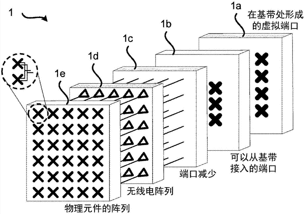
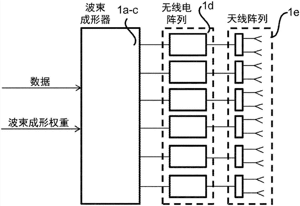
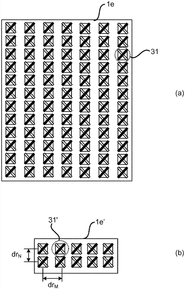
[0031] The antenna arrays and methods presented herein provide beam patterns with both desirable beam shapes and very good power utilization. Embodiments disclosed herein relate specifically to transmitting signals using beamforming antenna arrays. To obtain such a transmission, a network node, a method performed by the netwo...


PUM


Abstract

There is provided mechanisms for transmitting a signal using a beamforming antenna array. A method being is by a network node. The method comprises obtaining an indication for transmission of the signal requiring use of a partial antenna array of the antenna array, the partial antenna array requiring less than all of the physical elements of the antenna array for transmission. The method comprises forming virtual antenna elements for the partial antenna array, thereby reducing the full antenna aperture of the antenna array. The method comprises expanding weight factors applied to the virtual antenna elements by connecting each of the virtual antenna elements to at least part of all physical antenna elements of the antenna array such that the virtual antenna elements at least partly utilize the full antenna aperture. The method comprises initiating transmission of the signal using the array of the virtual antenna elements.

Description

technical field [0001] Embodiments presented herein relate to a method of transmitting signals using a beamforming antenna array, a network node, a computer program and a computer program product. Background technique [0002] In a communication network, it can be a challenge to obtain good performance and capacity for a given communication protocol, its parameters and the physical environment in which the communication network is deployed. [0003] One possible challenge of achieving good performance and capacity in a wireless communication network is configuring antennas of a network node for wireless communication whether to / from another network node and / or to / from wireless user terminals. [0004] For example, massive beamforming (i.e., beamforming using active antenna arrays orders of magnitude more than are used in current communication networks) is expected to be the radio access part of future fifth-generation (5G) communication networks technology components in . ...

Claims


Application Information

Patent Timeline
Patent Type & Authority Applications(China)
IPC IPC(8): H04B7/06
CPCH04B7/0617H04B7/0691H04B7/10H01Q1/246H01Q3/40H01Q21/0025
Inventor 斯文·彼得森弗雷德里克·阿什莉
Owner TELEFON AB LM ERICSSON (PUBL)
Why Eureka
Try Eureka