Electric power archive management device

A file management and power technology, applied in home appliances, applications, shelves, etc., can solve problems such as troublesome file search, and achieve the effect of convenient access.

Inactive Publication Date: 2017-12-05
RES INST OF ECONOMICS & TECH STATE GRID SHANDONG ELECTRIC POWER +1
8 Cites 5 Cited by

AI-Extracted Technical Summary

Problems solved by technology

At present, the storage of power files is generally stored directly ...

Abstract

An electric power archive management device is used for facilitating storage and usage of electric power archives. Traveling wheels are arranged on the bottom of a cabinet body. A framework is arranged in the cabinet body. Vertical plates are arranged in an inner cavity of the framework and divide the inner cavity of the framework into multiple chambers. A first lead screw is arranged on the back side of each chamber. A first nut is installed on each first lead screw in a matched mode. A first electric telescopic rod is fixed to each first nut. A stepping motor is arranged in the framework. A worm is arranged at the output end of the stepping motor. A worm wheel is fixed to the lower portion of each first lead screw. A push rod is fixed to each first electric telescopic rod. A built-in frame is fixed on the front side of each chamber. Partition boards are arranged in an inner cavity of each built-in frame. Archive boxes containing archives are placed on the partition boards. An oblique board is arranged at the open end of the framework. A belt conveyer is arranged at the lower end of the oblique board. A second electric telescopic rod is arranged on the right side of the cabinet body. A lifting mechanism, a transverse movement mechanism and a third electric telescopic rod are arranged on the front side of the framework. The electric power archive management device can facilitate storage and usage of archives.

Application Domain

Racks

Technology Topic

EngineeringBelt conveyor +1

Image

  • Electric power archive management device
  • Electric power archive management device
  • Electric power archive management device

Examples

  • Experimental program(1)

Example Embodiment

[0029] The present invention will be described in detail below in conjunction with the drawings.
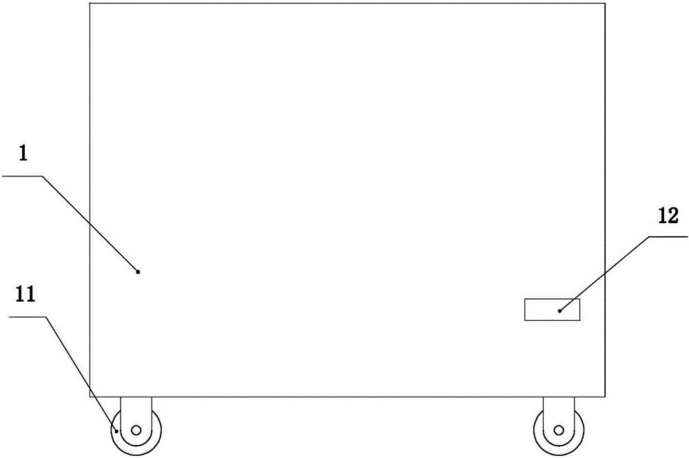
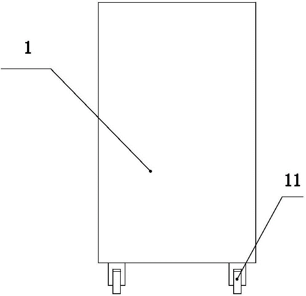
[0030] Such as figure 1 , figure 2 As shown, the cabinet 1 is the base of the present invention, and a walking wheel 11 is provided at the bottom of the cabinet. An exit 12 is provided on the front side wall of the cabinet, and the file box containing the files is pushed out from the exit.
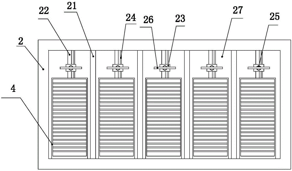
[0031] There is a frame 2 inside the cabinet, such as image 3 As shown, the frame is a rectangular hollow structure with an open front end. A number of vertical plates 21 are arranged on the inner side of the frame, and the vertical plates are arranged at equal intervals. The vertical plate divides the inner cavity of the frame into several chambers 27, such as Figure 5 As shown, a vertical first screw 22 is provided on the rear side of each chamber. Both ends of the first screw are fixed in the inner ring of the bearing 28, and the bearing is fixed in the upper and lower side walls of the frame. A first screw nut 23 is fitted on the first screw. To facilitate guidance, a guide rod 24 is provided on one side of the first screw. The guide rod is slidably connected to the first screw, and the guide rod is fixed in the frame. In order to drive the rotation of the first screw, a stepping motor is provided in the frame, and a worm is fixed at the output end of the stepping motor. The worm is rotated and installed in the chamber through a support, and a worm wheel is fixed on the first screw. , The worm and the worm gear mesh and cooperate, and the worm gear can be set to obtain a larger transmission ratio. The stepping motor, the worm gear and the worm constitute a driving mechanism for driving the rotation of the first screw.
[0032] A first electric telescopic rod 25 is fixed on the first screw nut, and a push rod 26 is fixed on the first electric telescopic rod. The push rod is a long rod, and a rubber pad is arranged on the acting surface of the push rod. A built-in frame 4 is provided on the front side of the chamber, and the built-in frame is fixed in the frame by bolts. The built-in frame is a hollow rectangular parallelepiped, and the front and rear sides of the built-in frame are open. In the inner cavity of the built-in frame, there are a number of partitions 41 arranged up and down at equal intervals. There are a number of independent placing cavities 42, and a file box containing files is placed in each placing cavity. When fetching files, the first electric telescopic rod drives the push rod to push the file box down.
[0033] Such as Figure 4 As shown, the open end of the frame is provided with an inclined plate 3, the upper end of the inclined plate is fixed at the lower part of the open end of the frame, and the function of the inclined plate is to catch the file box pushed down by the push rod. A belt conveyor 51 is provided at the lower end of the inclined plate, and the file box on the inclined plate slides down onto the belt conveyor and is conveyed to the right side of the cabinet via the belt conveyor. The end of the belt conveyor corresponds to the exit, and a second electric telescopic rod 5 is fixed on the right side wall of the cabinet, and the second electric telescopic rod corresponds to the exit. A push rod is also provided on the second electric telescopic rod. When the second electric telescopic rod is in motion, the file box can be pushed down from the belt conveyor, and the pushed file box is pushed out from the outlet.
[0034] In order to facilitate the control of the belt conveyor, a travel switch is provided on the right inner wall of the cabinet. The travel switch is connected with the signal of the controller, and the controller is connected with the signal of the belt conveyor, and the controller is also connected with the second electric telescopic Rod signal connection. When the file box on the belt conveyor reaches the exit position and is in contact with the travel switch, the travel switch sends a signal to the controller, and the controller controls the belt conveyor to stop, and at the same time the second electric telescopic rod moves, driving the push rod to move the file box Push down from the belt conveyor. The first screw, the first screw nut, the first electric telescopic rod, the second electric telescopic rod, the driving mechanism, the belt conveyor and the inclined plate constitute the taking assembly.
[0035] There is also a return assembly in the cabinet. The return assembly includes the support plate 6, the second screw nut 61, the second screw 7, the support 71, the first motor 72, the driving gear 73, the driven gear 74, and the sliding plate. 8. Sprocket 81, chain 83, second motor 82 and third electric telescopic rod 9, such as Figure 4 , Image 6 As shown, four pairs of supports 71 are provided in the inner cavity of the cabinet, a second screw 7 is provided between the two supports, and a second screw 61 is fitted on each second screw. , A horizontal support plate 6 is fixed between the four second screw nuts. In order to drive the synchronous rotation of the four second screw nuts, a first motor 72 is fixed on the cabinet, and the output end of the first motor is fixed There are driving gears 73, and driven gears 74 are respectively fixed on the four second screws, such as Picture 9 As shown, the driving gear is located between the four driven gears, and the driving gear and the four driven gears respectively mesh and cooperate. The second screw, the second screw nut, the driving gear, the driven gear and the first motor constitute a lifting mechanism.
[0036] A sliding plate 8 is slidably mounted on the support plate. A pair of sprockets 81 are arranged under the support plate. A chain 83 is arranged between the two sprockets. One of the sprockets rotates under the drive of a second motor 82. Both the sprocket and the sprocket are installed at the bottom of the support plate. A long hole 62 is provided on the support plate, and a protrusion is provided at the bottom of the sliding plate. The sliding plate is fixedly connected with the chain through the protrusions. When the second motor is activated, the sliding plate can be driven to move left and right relative to the supporting plate. A third electric telescopic rod 9 is fixed on the top of the skateboard, and the third electric telescopic rod faces the side where the frame is located. The third screw, the third nut, the sprocket, the chain and the second motor constitute a translation mechanism.
[0037] When working, the operator can input the required file number. The first screw in the chamber where the file is located drives the first electric telescopic rod to the corresponding position, and then the first electric telescopic rod moves to push out the corresponding file box. The file box slides down on the belt conveyor along the inclined plate. The belt conveyor moves to transport the file box to the rightmost side of the cabinet, and then the second electric telescopic rod action pushes the file box out of the belt conveyor, and the file box comes out through the outlet. When you need to put the files in the file box back into the cabinet, first put the file box on the slide, input the number of the file, and the controller controls the second motor to move the slide to the front of the corresponding chamber. The first motor moves to make the file box located directly in front of the corresponding placing cavity, and then the third electric telescopic rod moves to push the file box into the corresponding placing cavity.

PUM

no PUM

Description & Claims & Application Information

We can also present the details of the Description, Claims and Application information to help users get a comprehensive understanding of the technical details of the patent, such as background art, summary of invention, brief description of drawings, description of embodiments, and other original content. On the other hand, users can also determine the specific scope of protection of the technology through the list of claims; as well as understand the changes in the life cycle of the technology with the presentation of the patent timeline. Login to view more.

Similar technology patents

Novel tool storage box

InactiveCN103286760AEasy accessPrevent tool wear
Owner:SUZHOU SUTENG ELECTRONICS TECH

Shale gas content calculation method

ActiveCN110672813AThe process is simple and convenienteasy access
Owner:CHINA PETROLEUM & CHEM CORP +1

Classification and recommendation of technical efficacy words

  • easy access

Soil remediation treatment device

ActiveCN108187850Aconstant soil volumeeasy access
Owner:刘艳燕

Medical foldable bedside cabinet

Owner:苏州优点优唯医疗科技有限公司

Underground locomotive escape door device

ActiveCN101062686Agentle rampeasy access
Owner:CHANGZHOU CHANGQING TRAFFIC TECH
Why Eureka
Try Eureka