Screw conveyor

A conveyor and screw technology, applied in the direction of conveyor objects, transportation and packaging, can solve the problems of short service life of the screw conveying mechanism, reduce the screw conveying efficiency, and the screw cannot fall in, so as to avoid low switching accuracy and avoid jamming. , Improve the effect of installation rhythm

Pending Publication Date: 2017-12-08
SHANGHAI JINGZHI IND CO LTD
View PDF10 Cites 11 Cited by
  • Summary
  • Abstract
  • Description
  • Claims
  • Application Information

AI Technical Summary

Problems solved by technology

[0002] At present, the existing screw conveying mechanism generally has the function of sorting the screws, and the existing screw conveying machine is prone to jamming when conveying the screws, which will easily lead to the short life of the screw conveying mechanism and the scrap rate after maintenance. In addition, when the screws are out of the warehouse, mechanisms such as vibrating discs are generally used in the prior art, and the screws are sorted according to the vibrating discs to jump into the track. When the vibration of the vibrating disc is unstable, it is easy for the screws not to fall into the The specified track to complete the delivery, thus reducing the efficiency of screw delivery

Method used


Image

  • Screw conveyor
  • Screw conveyor
  • Screw conveyor

Examples


Embodiment Construction

[0058] In order to enable those skilled in the art to better understand the technical solution of the present invention, the technical solution of the present invention will be further described below in conjunction with the accompanying drawings and through specific implementation methods.

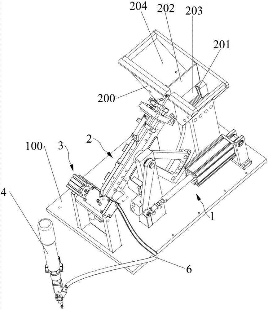
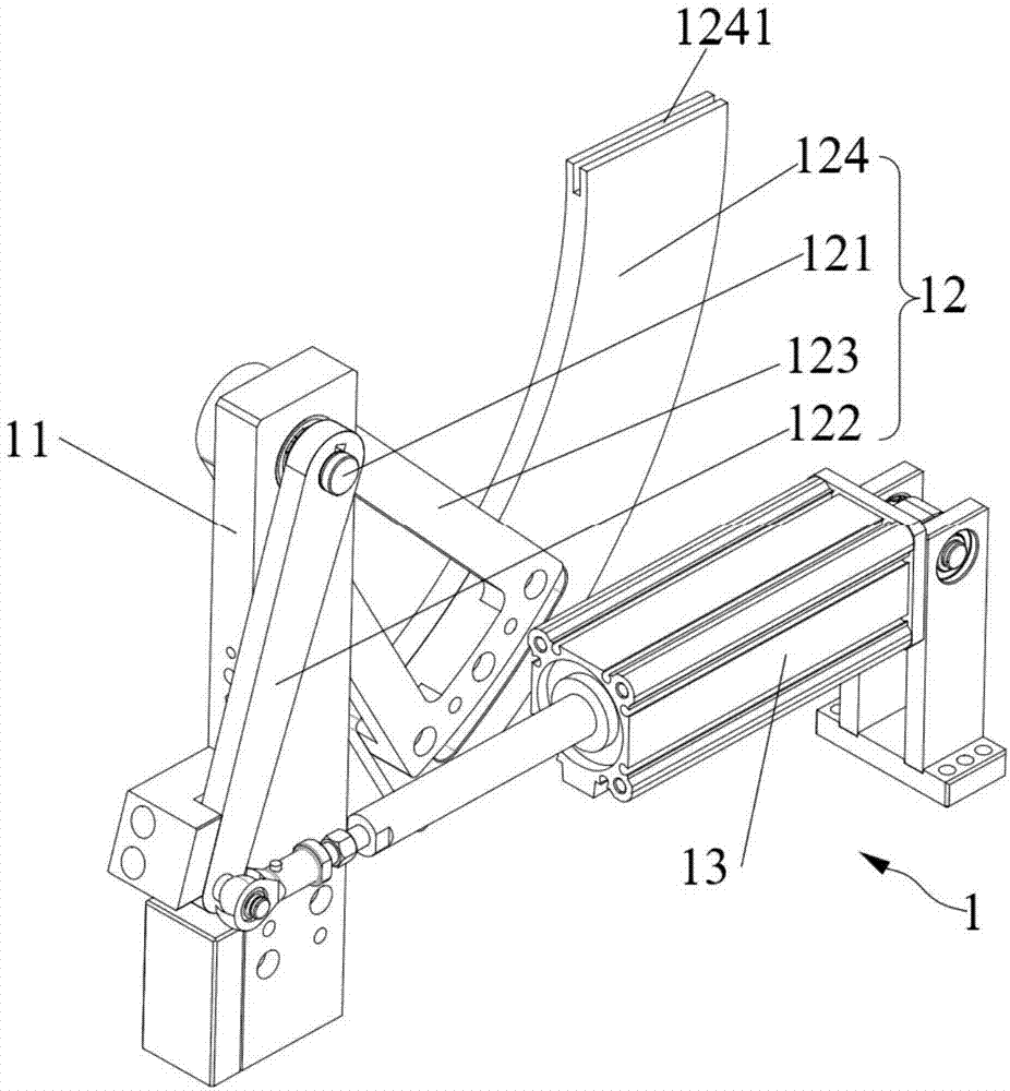
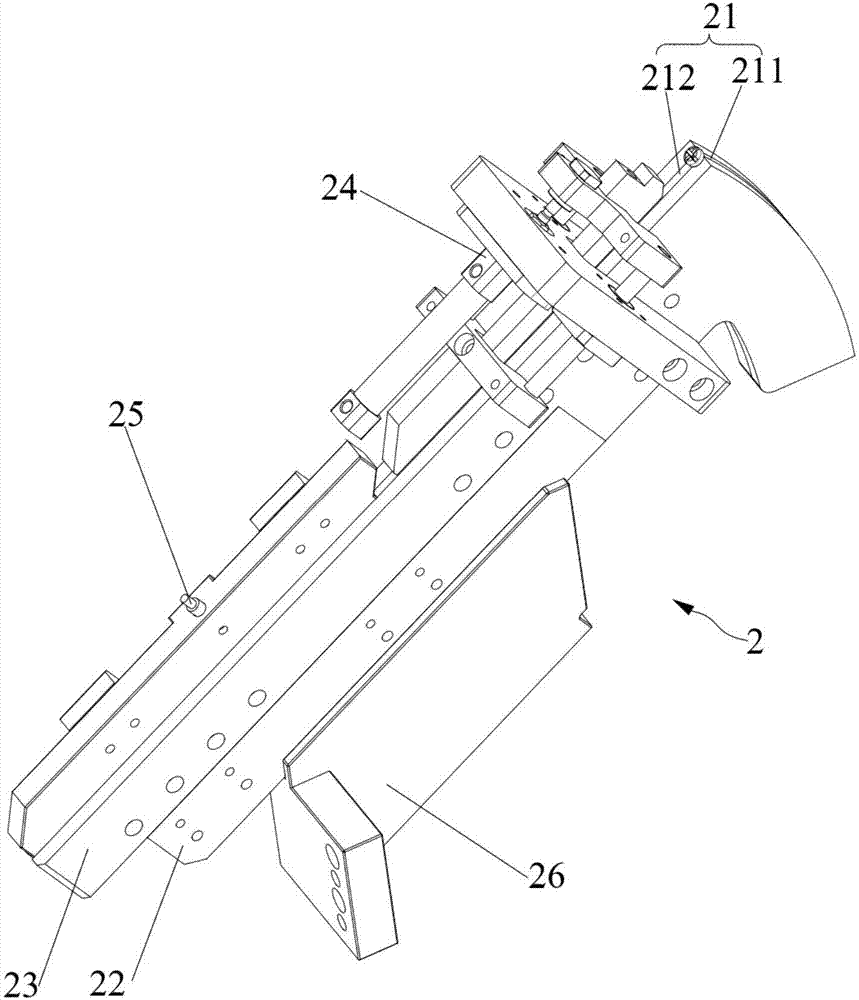
[0059] This embodiment provides a screw conveyor, such as Figure 1-Figure 10As shown, it includes: a base plate 100; a silo 200, which is installed on the base plate 100; a feeding drive mechanism 1, including a support frame 11 fixed on the base plate 100, and a support frame 11 rotatably connected The swing assembly 12, and the drive cylinder 13 connected to the bottom plate 100, the drive cylinder 13 drives the swing assembly 12 to swing, so as to push the screws in the feed bin 200 to move upward; the discharge mechanism 2, which tilts Set on the support frame 11, one end of the discharge mechanism 2 passes through one side of the silo 200, the discharge mechanism 2 is provided with ...


PUM


Abstract

The invention relates to a screw conveyor and belongs to the technical field of screw installation. According to the screw conveyor, structures are installed compactly, mechanisms can be tightly matched with one another, screws can be discharged in order, the situation that the screws are clamped is avoided, and therefore the conveying efficiency of the screws is improved, and the installation rhythm of the screws is improved. By means of the switching mechanism, the switching efficiency of the switching mechanism is improved, the situations that in the prior art, the switching precision is low and the switching efficiency is low due to the fact that the structure of a screw switching mechanism is complex are avoided, and the precision requirement of the screw switching mechanism during screw switching is guaranteed. By means of a material channel of the feeding drive mechanism, the sequence of discharging of the screws is guaranteed, and the occurrence of the clamping situation is avoided.

Description

technical field [0001] The invention relates to the technical field of screw conveying, in particular to a screw conveying machine. Background technique [0002] At present, the existing screw conveying mechanism generally has the function of sorting the screws, and the existing screw conveying machine is prone to jamming when conveying the screws, which will easily lead to the short life of the screw conveying mechanism and the scrap rate after maintenance. In addition, when the screws are out of the warehouse, mechanisms such as vibrating discs are generally used in the prior art, and the screws are sorted according to the vibrating discs to jump into the track. When the vibration of the vibrating disc is unstable, it is easy for the screws to not fall into the The designated track is used to complete the delivery, thereby reducing the screw delivery efficiency. Contents of the invention [0003] The object of the present invention is to propose a screw conveyor that ca...

Claims


Application Information

Patent Timeline
Patent Type & Authority Applications(China)
IPC IPC(8): B65G47/82B65G47/74B65G47/14
CPCB65G47/1407B65G47/74B65G47/82
Inventor 李峰会邓南建杜字林胡建雷汪伟
Owner SHANGHAI JINGZHI IND CO LTD
Why Eureka
Try Eureka