Fixed-point self-locking mechanism

A self-locking and block-tightening technology, applied in mechanical equipment, fixtures, etc., can solve the problems of reducing the degree of automation of products, difficult to maintain accuracy, and inability to insert pins, so as to ensure positioning accuracy and repeat positioning accuracy. The effect of long-term positioning accuracy maintenance and reliable work

Active Publication Date: 2017-12-08
GUIZHOU AEROSPACE TIANMA ELECTRICAL TECH
View PDF9 Cites 4 Cited by
  • Summary
  • Abstract
  • Description
  • Claims
  • Application Information

AI Technical Summary

Problems solved by technology

Since most of the loads are erected by hydraulic cylinders, it is difficult to achieve the maintenance accuracy of erecting in place only by hydraulic cylinders and hydraulic locks; if a mechanical latch structure is used, it will be difficult for the latch to be erected in place and placed for a long time. Pull out, the plug will be deformed due to long-term use, resulting in the plug can not be inserted
Due to the large working angle, it is difficult to achieve manual latching
At the same time, the manual latch also reduces the degree of automation of the product

Method used


Image

  • Fixed-point self-locking mechanism
  • Fixed-point self-locking mechanism

Examples


Embodiment Construction

[0024] The technical solution of the present invention is further described below, but the scope of protection is not limited to the description.

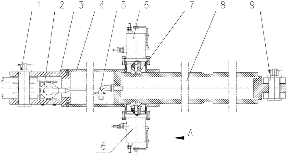
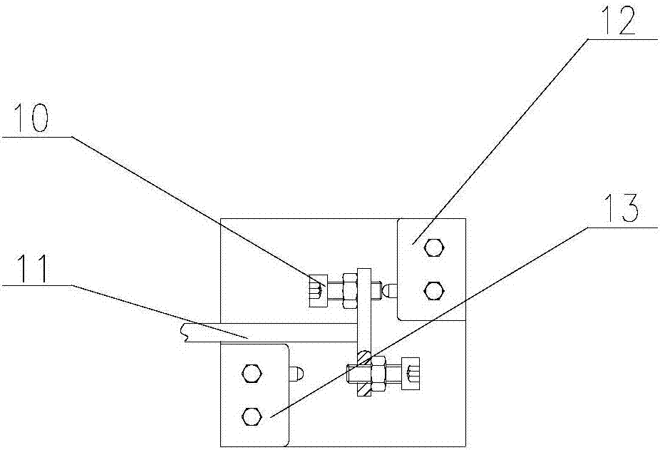
[0025] Such as figure 1 , figure 2 A fixed-point self-locking mechanism shown includes an outer cylinder flange 3, an outer cylinder 4, a rope puller (5), a locking cylinder 6, a universal locking block 7, and an inner cylinder 8; the outer cylinder flange 3 and the end of the outer cylinder 4 are connected and fixed, and the outer cylinder 4 is covered with an inner cylinder 8; a locking cylinder 6 is fixed on the outer cylinder 4, and the inner end of the locking cylinder 6 is connected with a universal locking block 7, and the locking cylinder 6 A trigger 10 and a sensor 11 are arranged on the top, and the start and stop of the locking cylinder 6 can be controlled by the trigger 10 and the sensor 11; the inner cylinder 8 is provided with an annular slot, and the shape of the annular slot matches the universal locking block 7 ...


PUM


Abstract

The invention provides a fixed-point self-locking mechanism. The fixed-point self-locking mechanism comprises an outer drum flange, an outer drum, a locking oil cylinder, a universal locking block and an inner drum. The outer drum flange and the end part of the outer drum are connected and fixed. The inner drum is arranged in the outer drum in a sleeved mode. The outer drum is fixedly provided with the locking oil cylinder. The inner end part of the locking oil cylinder is connected with the universal locking block. The locking oil cylinder is provided with a trigger and an inductor, and starting and stopping of the locking oil cylinder is controlled by the trigger and the inductor. An annular clamping groove is formed in the inner drum. The shape of the annular clamping groove is matched with the shape of the universal locking block. According to the fixed-point self-locking mechanism, locking is achieved by using a mode of the annular clamping groove, the problem that an inserted pin is hard to be pulled out due to long-time stress of a traditional inserted pin mode is avoided, an in-place state of load is detected by using a constant force opening instrument, control is easy, and working is reliable.

Description

technical field [0001] The invention relates to a fixed-point self-locking mechanism. Background technique [0002] In many military engineering machinery, many large loads need to be erected to a certain angle for work, so it is necessary to lock the load after it is erected to the working angle, and the accuracy remains unchanged after locking. Because most of the loads are erected by hydraulic cylinders, it is difficult to achieve the maintenance accuracy of erecting in place only by hydraulic cylinders and hydraulic locks; if a mechanical latch structure is used, it will be difficult for the latch to be erected in place and placed for a long time. If it is pulled out, the pin will also be deformed due to long-term use, resulting in the pin not being able to be inserted. Due to the large working angle, it is difficult to realize by manual latching. Simultaneously, manual latch also reduces the degree of automation of the product. [0003] Several difficulties need to b...

Claims


Application Information

Patent Timeline
Patent Type & Authority Applications(China)
IPC IPC(8): F16B1/04F16B1/00
CPCF16B1/04F16B2200/89F16B2200/99F16B2200/95
Inventor 喻会福吴地勇叶华
Owner GUIZHOU AEROSPACE TIANMA ELECTRICAL TECH
Why Eureka
Try Eureka