Badminton net rack capable of winding and protecting badminton net
A badminton and net surface technology, which is applied in the field of badminton net surface racks, can solve the problems of short service life of the net surface, inability to wind the net surface, waste of badminton court ground resources, etc.
- Summary
- Abstract
- Description
- Claims
- Application Information
AI Technical Summary
Problems solved by technology
Method used
Image

Examples
Embodiment 1
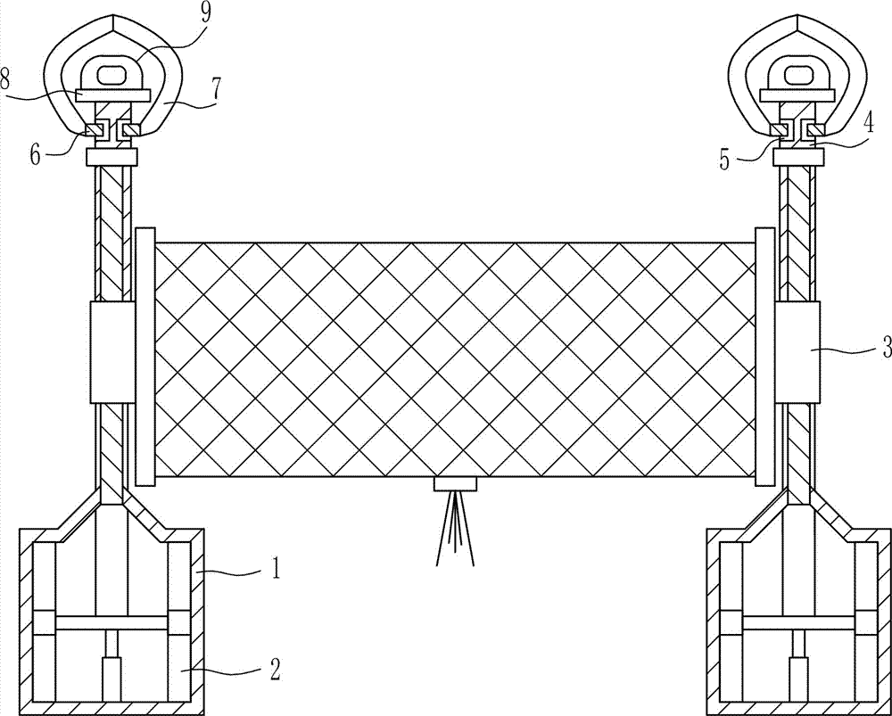
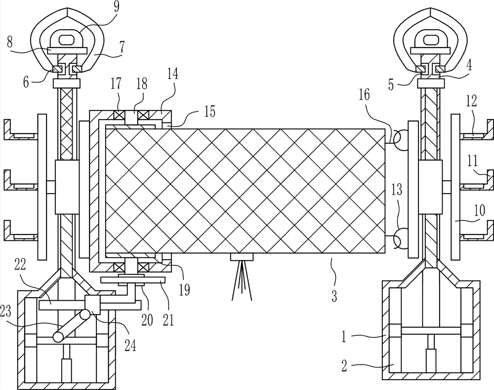
[0034] A badminton net frame capable of wrapping and protecting the net surface, such as Figure 1-7 Shown, comprise installation box 1, driving mechanism 2 and lifting mechanism 3, ground left and right symmetrically be connected with installation box 1, all be provided with driving mechanism 2 in the installation box 1, be connected with lifting mechanism 3 on the driving mechanism 2.
Embodiment 2
[0036] A badminton net frame capable of wrapping and protecting the net surface, such as Figure 1-7 Shown, comprise installation box 1, driving mechanism 2 and lifting mechanism 3, ground left and right symmetrically be connected with installation box 1, all be provided with driving mechanism 2 in the installation box 1, be connected with lifting mechanism 3 on the driving mechanism 2.
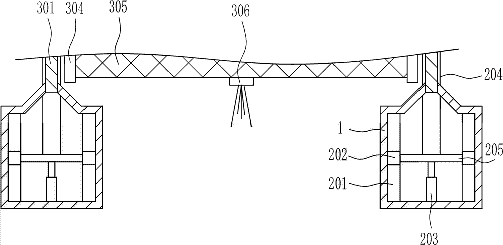
[0037] The driving mechanism 2 includes a first slide rail 201, a first slide block 202, an electric push rod 203, a lifting rod 204 and a lifting plate 205. The first slide rail 201 is symmetrically connected to the left and right in the installation box 1, and the first slide rail 201 The upper part is slidingly connected to the first slider 202, the inner side of the first slider 202 is connected with a lifting plate 205, and the middle of the top of the lifting plate 205 is connected with a lifting rod 204, and the lifting rod 204 is located at the rear side of the installation box 1. An ...
Embodiment 3
[0039] A badminton net frame capable of wrapping and protecting the net surface, such as Figure 1-7 Shown, comprise installation box 1, driving mechanism 2 and lifting mechanism 3, ground left and right symmetrically be connected with installation box 1, all be provided with driving mechanism 2 in the installation box 1, be connected with lifting mechanism 3 on the driving mechanism 2.
[0040] The driving mechanism 2 includes a first slide rail 201, a first slide block 202, an electric push rod 203, a lifting rod 204 and a lifting plate 205. The first slide rail 201 is symmetrically connected to the left and right in the installation box 1, and the first slide rail 201 The upper part is slidingly connected to the first slider 202, the inner side of the first slider 202 is connected with a lifting plate 205, and the middle of the top of the lifting plate 205 is connected with a lifting rod 204, and the lifting rod 204 is located at the rear side of the installation box 1. An ...
PUM
 Abstract
Description
Claims
Application Information
 - R&D
- Intellectual Property
- Life Sciences
- Materials
- Tech Scout
- Unparalleled Data Quality
- Higher Quality Content
- 60% Fewer Hallucinations
Browse by: Latest US Patents, China's latest patents, Technical Efficacy Thesaurus, Application Domain, Technology Topic, Popular Technical Reports.
© 2025 PatSnap. All rights reserved.Legal|Privacy policy|Modern Slavery Act Transparency Statement|Sitemap|About US| Contact US: help@patsnap.com