Supercharge Your Innovation With Domain-Expert AI Agents!

Cable fixing comb and manufacturing method thereof

A technology for fixing combs and arranging wires, which is applied in the direction of busbar/line layout, substation/switch layout details, electrical components, etc., and can solve problems such as not being able to achieve the best fixed position

Active Publication Date: 2019-11-01
ABB (SCHWEIZ) AG
View PDF5 Cites 0 Cited by
  • Summary
  • Abstract
  • Description
  • Claims
  • Application Information

AI Technical Summary

Problems solved by technology

This results in a wire with high stiffness that does not reach an optimal fixation position

Method used


Image

  • Cable fixing comb and manufacturing method thereof
  • Cable fixing comb and manufacturing method thereof
  • Cable fixing comb and manufacturing method thereof

Examples


Embodiment Construction

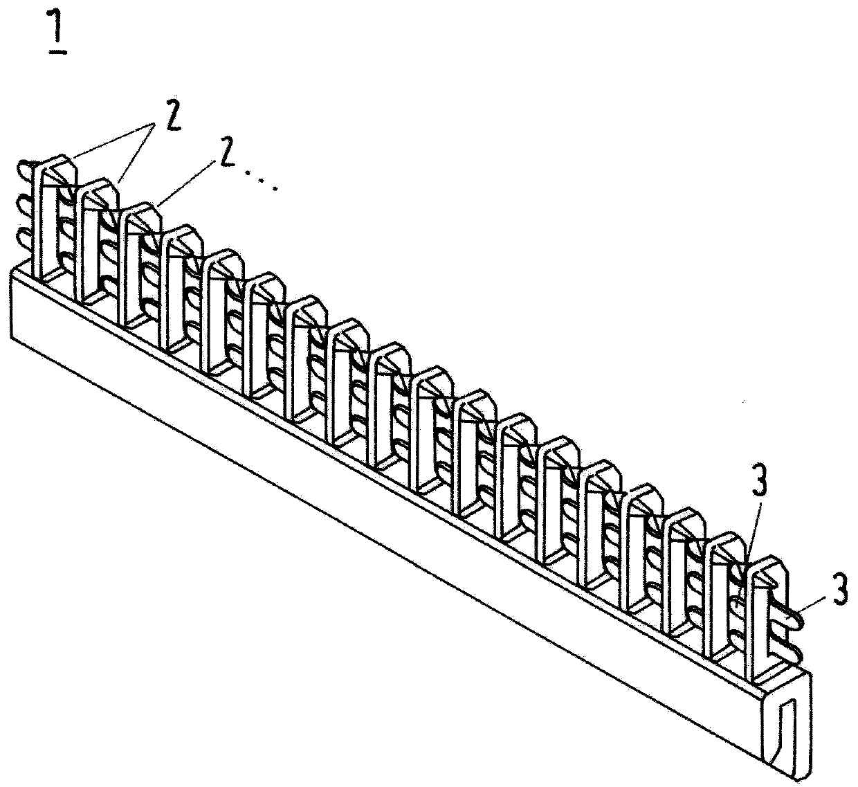
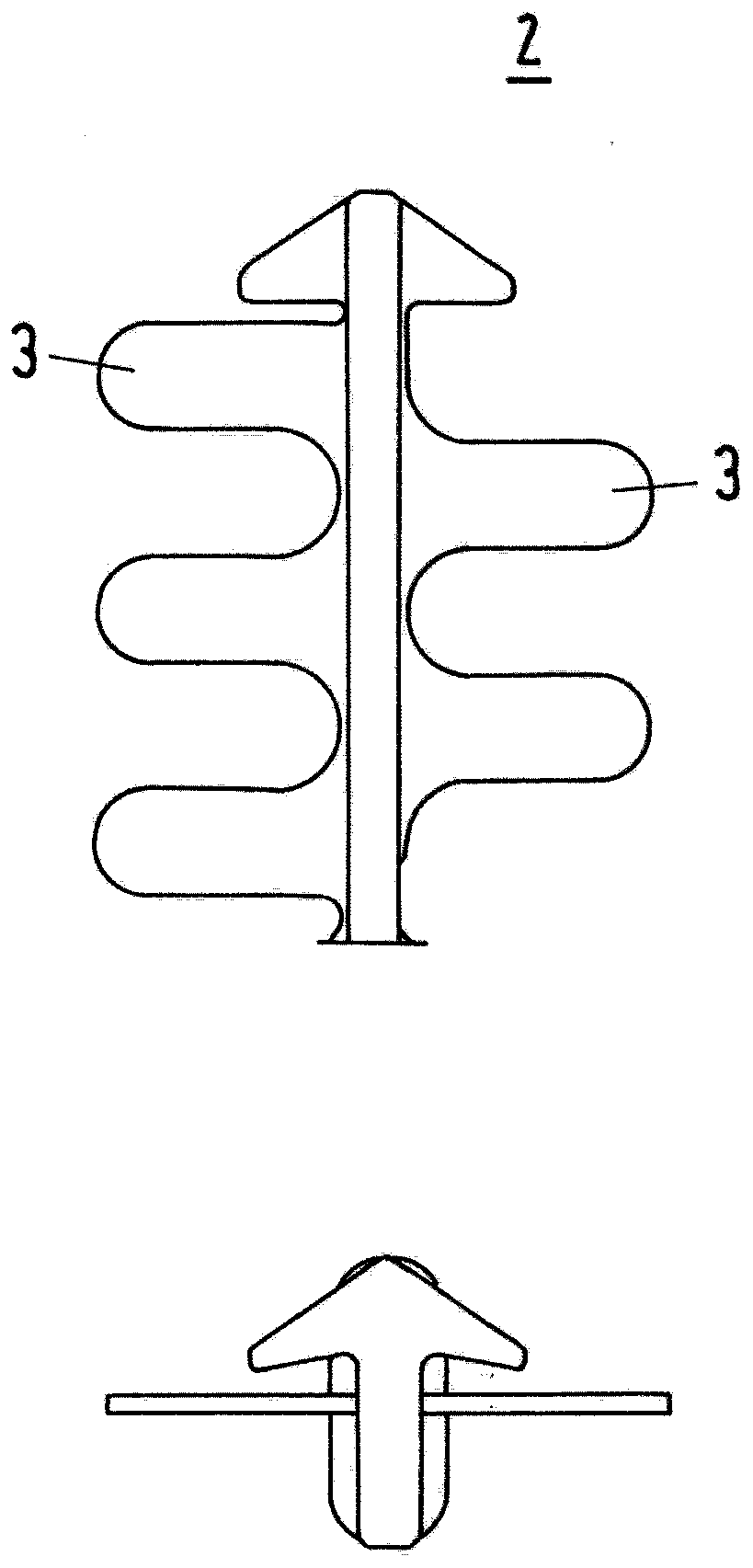
[0017] figure 1 Shown is a routing comb 1 with teeth 2 arranged in parallel. A slit flag 3 is positioned between the teeth. The wire will be inserted between the teeth and pushed towards the socket 4 from above. With this action, the slit flag will be deployed. After the wire reaches its final position between the teeth, the portion of the slit flag above the wire will bend back and secure the final position of the wire.

[0018] figure 2 shown from the rear figure 1 Cable 1 shown.

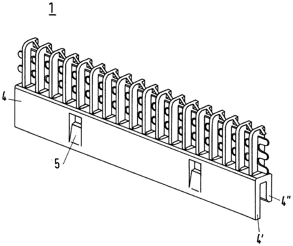
[0019] The socket 4 has a cross-section of a U-profile in the form that one side 4' of the socket is longer than the other side 4" of the socket.

[0020] Furthermore, in the longer side 4' of the socket 4, a snap element 5 is arranged integrally therein.

[0021] By means of these snap-in elements 5, the cable fixing comb 1 can be fixed on a support plate, for example in a low-voltage chamber.

[0022] image 3 A detailed view of a single tooth 2 of the wire fixing comb 1 is shown. It ...


PUM


Abstract

Wire arrangement fixation comb (1) to fix the wire arrangement in low voltage compartment, comb consist of a number of parallel teeth (2), between which the wires or cables has to be arranged, wherein each tooth is provided on both flanks with bendable or flexible slitted flags (3), which are able to fix the wires in position, after they can be inserted between the teeth of the fixation comb, according to the preamble of claim 1. In order to enhance the fixation or the stiffness of the wire fixation, the invention is, that the flags on both sides are slitted in alternating wavelike line, in such, that the wavelined flag of one flank of a first tooth is shifted, and complementarily fits into the wavelined flag of a second directly neigboring tooth, and so on.

Description

technical field [0001] The invention relates to a cable fixing comb for fixing cables in a low-pressure chamber, the comb is composed of a plurality of parallel teeth, between which the wire or cable will be arranged, wherein each tooth is provided with movable A curved or flexible slit flag capable of holding the thread in place after the thread can be inserted between the teeth of the fixed comb. The invention also relates to a method of manufacturing the fixed comb. Background technique [0002] For example, the wiring in the low-voltage compartment of the switchgear is a prior art in this field. An example of this is disclosed in US 2015 / 0214699A1. [0003] This comb will be fixed on a strip-like support element in the low pressure chamber. This comb consists of a number of parallel teeth between which the wire or cable will be arranged. Each tooth is provided on both sides with a bendable or flexible slit flag capable of holding the thread in place after they are ins...

Claims


Application Information

Patent Timeline
Patent Type & Authority Patents(China)
IPC IPC(8): H02B1/20
CPCH02B1/202
Inventor L·威丁格
Owner ABB (SCHWEIZ) AG
Features
  • R&D
  • Intellectual Property
  • Life Sciences
  • Materials
  • Tech Scout
  • Unparalleled Data Quality
  • Higher Quality Content
  • 60% Fewer Hallucinations
Learn More