
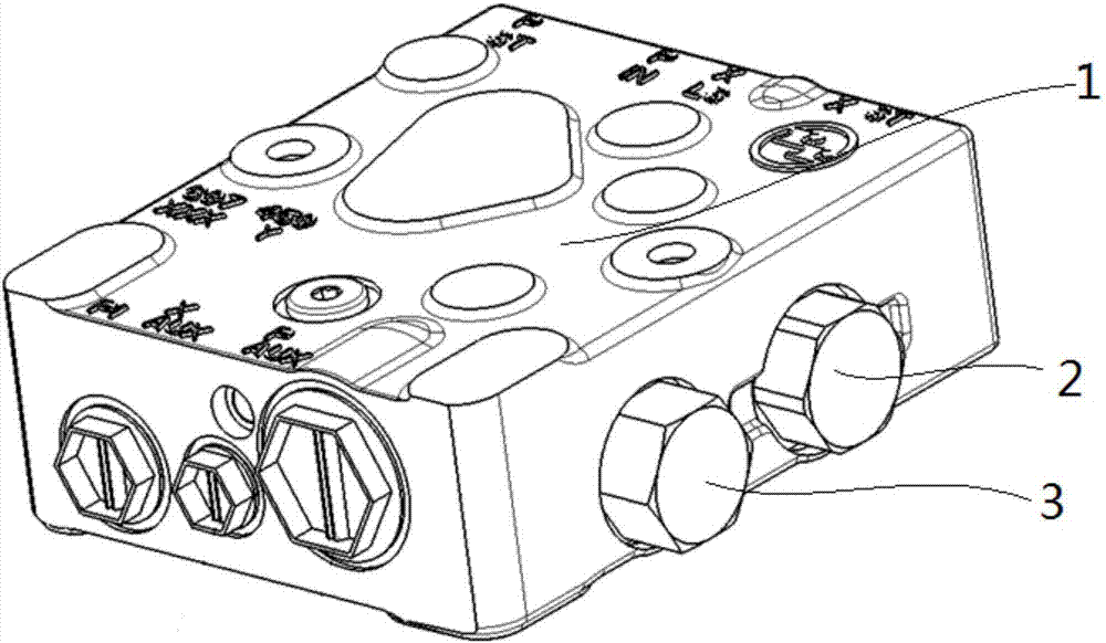
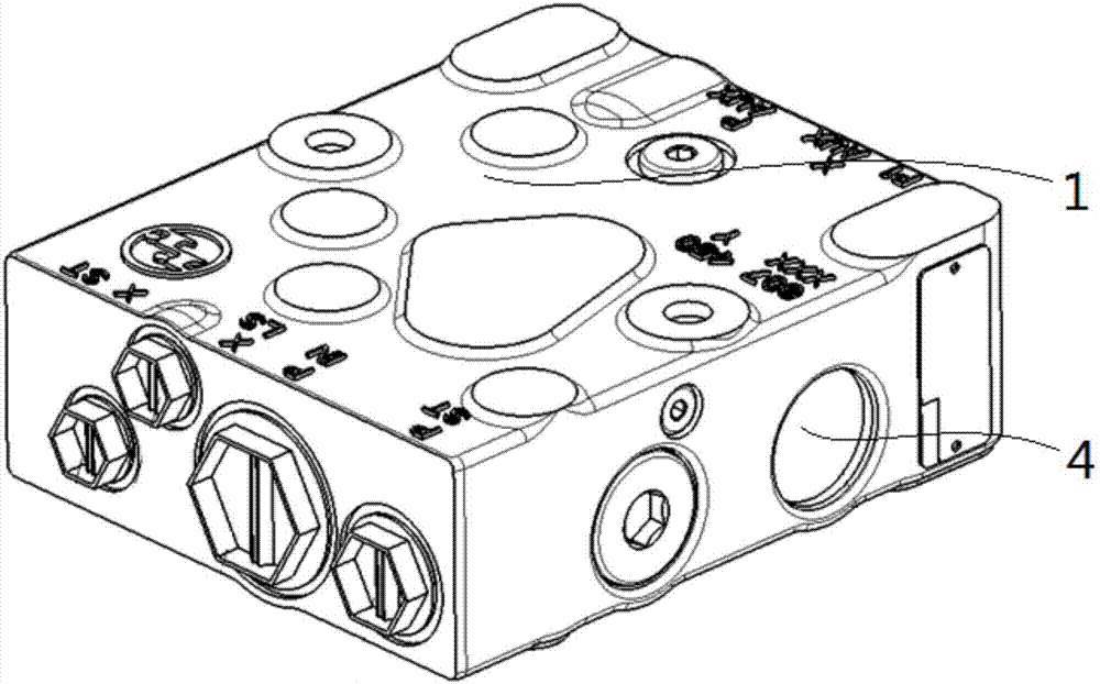
Flow dividing valve block

A diverter valve, valve block technology, applied in the direction of fluid pressure actuating device, servo motor, servo motor assembly, etc., can solve the problem that the oil volume of the steering mechanism cannot be guaranteed, etc.

Pending Publication Date: 2017-12-19
LOVOL HEAVY IND CO LTD
View PDF0 Cites 0 Cited by
  • Summary
  • Abstract
  • Description
  • Claims
  • Application Information

AI Technical Summary

Problems solved by technology

[0003] The technical problem to be solved by the present invention is to provide a diverter valve block to solve the problem that the oil quantity of the steering mechanism cannot be guaranteed

Method used


Image

  • Flow dividing valve block
  • Flow dividing valve block
  • Flow dividing valve block

Examples


Embodiment Construction

[0016] The principles and features of the present invention are described below in conjunction with the accompanying drawings, and the examples given are only used to explain the present invention, and are not intended to limit the scope of the present invention.

[0017] In the description of the present invention, it should be understood that the orientation or positional relationship indicated by the terms "upper", "lower", "center", "inner", "outer", "top", "bottom" etc. are based on the attached The orientation or positional relationship shown in the figure is only for the convenience of describing the present invention and simplifying the description, and does not indicate or imply that the referred device or element must have a specific orientation, be constructed and operated in a specific orientation, and therefore cannot be construed as a reference to this invention. Invention Limitations.

[0018] In the description of the present invention, it should be noted that ...


PUM


Abstract

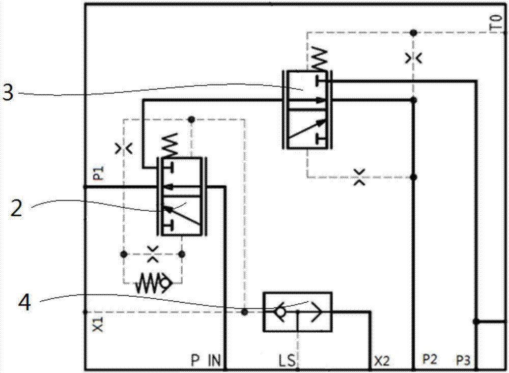
The invention relates to the field of hydraulic valves, in particular to a flow dividing valve block. The flow dividing valve block comprises a valve block body and a preferential flow valve element. The preferential flow valve element is arranged on the side surface of the valve block body and connected with a main pump, a steering mechanism and a traveling mechanism through oil ways. The preferential flow valve element supplies oil to the steering mechanism preferentially. When a hydraulic system works, the main pump supplies oil to all execution mechanisms, due to the facts that the preferential flow valve element is connected with the steering mechanism and the traveling mechanism through the oil ways, and the preferential flow valve element supplies oil to the steering mechanism preferentially, the effect that no matter how the pressure of a non-preferential port changes, the requirement of a preferential port is met by system flow preferentially as long as the preferential port has the requirement is guaranteed by the preferential flow valve element through flow control, and thus, the effect that functions of a steering system of a working device are preferential is guaranteed. On the premise that the effect that the functions of the steering system are preferential is guaranteed, the hydraulic oil flow of the traveling mechanism is secondly preferential, and accordingly, the oil flow requirement of the steering mechanism in the working device is met.

Description

technical field [0001] The invention relates to the field of hydraulic valves, in particular to a diverter valve block. Background technique [0002] At present, the hydraulic steering process of low-speed vehicles is like this (taking right steering as an example): when the steering wheel does not move, the spool is in a neutral position relative to the valve sleeve. The steering gear enters the oil cylinder, pushes the piston to move to the right, the piston rod pushes the steering rocker arm to swing, deflects the front wheel to the right, and at the same time returns the steering gear spool, and the spool returns to the neutral position, and the piston stops at this position No longer move to the right, that is, the steering wheel realizes servo control of the wheels. If continuous right steering is required, the steering wheel should continue to be turned to the right. Since one pump drives multiple actuators in the tractor, the uneven flow distribution of the system le...

Claims


Application Information

Patent Timeline
Patent Type & Authority Applications(China)
IPC IPC(8): F15B13/02F15B11/16
CPCF15B11/162F15B13/02F15B13/028F15B2013/002
Inventor 姜维张继伟邵年张心雨赵兰欣张继东
Owner LOVOL HEAVY IND CO LTD
Learn More