Shutter vehicle shutter-turning mechanism and lifting transmission system comprising same

The technology of lifting transmission and louver car is applied in the field of radial tire manufacturing, which can solve the problems of easy deformation or damage of the tread, high labor intensity of workers, and unfavorable tire quality.

Pending Publication Date: 2017-12-22
NANJING LONSON AUTOMATION EQUIP TECH
View PDF2 Cites 0 Cited by
  • Summary
  • Abstract
  • Description
  • Claims
  • Application Information

AI Technical Summary

Problems solved by technology

[0002] China has become a big tire manufacturing country in the world, but many operations on the production line are still done manually. The labor intensity of the workers is very high, and the tread is easily deformed or damaged, which is not conducive to the quality of the tire. In view of the current increase in labor costs, it is an inevitable choice to replace labor with machinery.

Method used


Image

  • Shutter vehicle shutter-turning mechanism and lifting transmission system comprising same
  • Shutter vehicle shutter-turning mechanism and lifting transmission system comprising same
  • Shutter vehicle shutter-turning mechanism and lifting transmission system comprising same

Examples


Embodiment 1

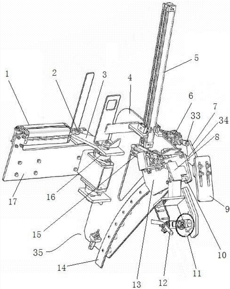
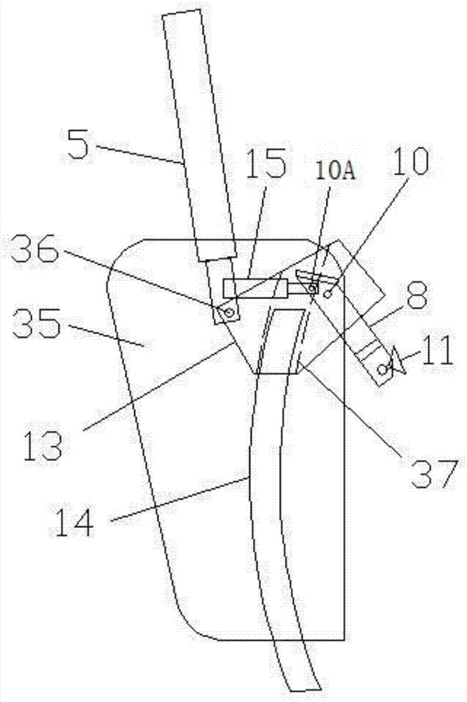
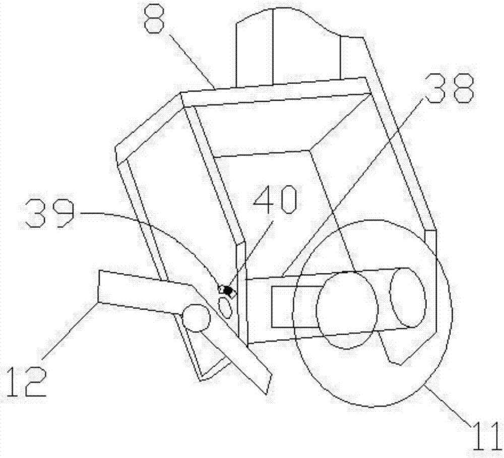
[0022] Depend on Figure 1-Figure 3 The page-turning mechanism of the shutter car shown includes a fixed seat 17 for driving the cylinder 1 of the rotary frame, a rotary frame 35 hinged to the fixed seat 17 through the hinge axis A16, a lifting cylinder 5 vertically arranged on the rotary frame 35, and a lifting cylinder 5 arranged vertically on the rotary frame. Cylinder 5 drives the sucker seat 13 of lifting, the sucker driving cylinder 15 that is arranged on the sucker seat 13, the sucker connecting frame 8 that is hinged with the sucking cup seat 13 by hinge shaft B10, the sucking cup 11 that is provided with on the sucking cup connecting frame 8 and a supporting mechanism.

[0023] The rotary frame drive cylinder 1 is horizontally arranged on the left and right sides, the left end of the cylinder body of the rotary frame drive cylinder 1 is fixed or hinged on the fixed seat 17, the telescopic rod of the rotary frame drive cylinder 1 extends horizontally to the right and ca...

Embodiment 2

[0035] Depend on Figure 4-Figure 7 The lifting transmission system shown includes a main frame 28 provided with a lifting platform, a lifting device that drives the lifting platform up and down, and two shutter vehicle page-turning mechanisms 32 described in Embodiment 1, the fixed seat 17 of the shutter vehicle page-turning mechanism 32 and Lifting platform is fixedly connected, and two louver car page-turning mechanisms 32 are arranged at intervals.

[0036] The main frame 28 is a cube-shaped frame structure. Described elevating platform comprises upper beam 24 and the rectangular frame 26 that horizontally arranges, and upper beam 24 is fixedly connected with rectangular frame 26, and rectangular frame 26 comprises front beam 25, rear beam 27, left connecting plate 42 and right connecting plate 43, and front beam 25 and rear crossbeam 27 all are left and right horizontal extensions, and left connecting plate and right connecting plate all are front and rear horizontal ext...


PUM


Abstract

The invention discloses a shutter vehicle shutter-turning mechanism and a lifting transmission system comprising the same and belongs to the technical field of radial tire manufacturing. The shutter vehicle shutter-turning mechanism comprises a fixing seat provided with a rotating frame driving cylinder, a rotating frame hinged to the fixing seat through a hinging shaft A, a lifting cylinder vertically arranged on the rotating frame, a sucker seat driven to ascend and descend by the lifting cylinder, a sucker driving cylinder arranged on the sucker seat, a sucker connecting frame hinged to the sucker seat through a hinging shaft B, a sucker arranged on the sucker frame and a supporting mechanism. The lifting transmission system comprises a main rack provided with a lifting platform, a lifting device driving the lifting platform to ascend and descend and the shutter vehicle shutter-turning mechanism. The shutter vehicle shutter-turning mechanism can automatically turn shutters of a shutter vehicle.

Description

technical field [0001] The invention belongs to the technical field of radial tire manufacture, and in particular relates to a page-turning mechanism of a louver car and a lifting transmission system formed therefrom. Background technique [0002] China has become a big tire manufacturing country in the world, but many operations on the production line are still done manually. The labor intensity of the workers is very high, and the tread is easily deformed or damaged, which is not conducive to the quality of the tire. In view of the current increase in labor costs, it is an inevitable choice to replace labor with machinery. . [0003] The treads of radial tires need to be stored on the shutter car one by one, and a radial tire tread needs to be clamped between the two leaf plates of the shutter car. In the prior art, this work is done manually. Contents of the invention [0004] The object of the present invention is to provide a leaf-turning mechanism for a louver that ...

Claims


Application Information

Patent Timeline
IPC IPC(8): B62B3/04B62B3/10
CPCB62B3/04B62B3/10
Inventor 黄福旺李新春杜宇涛
Owner NANJING LONSON AUTOMATION EQUIP TECH
Why Eureka
Try Eureka