Drivable working machine and method for operating same

A working machine, working position technology, applied in the direction of earth movers/shovels, cranes, transportation and packaging, etc., to achieve the effect of reduced downtime, high deflection stiffness

Inactive Publication Date: 2018-01-02
PUTZMEISTER ENG
View PDF4 Cites 0 Cited by
  • Summary
  • Abstract
  • Description
  • Claims
  • Application Information

AI Technical Summary

Problems solved by technology

The disadvantage here is that the tail structure with the filling funnel protrudes far back

Method used


Image

  • Drivable working machine and method for operating same
  • Drivable working machine and method for operating same
  • Drivable working machine and method for operating same

Examples


Embodiment Construction

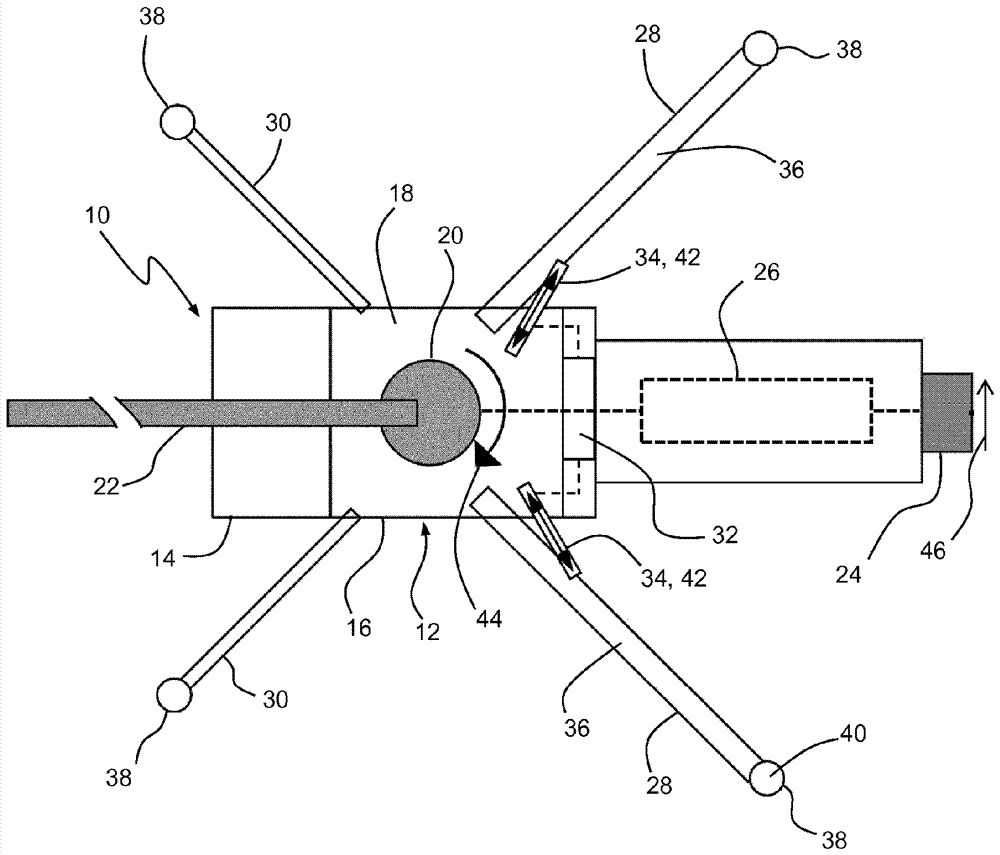
[0026] exist figure 1 The truck-mounted concrete pump 10 illustrated in includes a transport vehicle 12 with a cab 14 and a frame 16 , a superstructure frame (Aufbaurahmen) or load-carrying structure 18 , a multi-linkage that can be rotated about a vertical axis (Hochachse) by means of a rotation mechanism 20 Mehrgliedrigen concrete distribution rod 22, a delivery pump 26 configured as a double-cylinder piston pump for conveying liquid concrete, coupled between the filling funnel 24 and said concrete distribution rod 22, and a plurality of support legs 28, 30 It serves to support the load-bearing structure 18 in a working position provided for the concrete pouring operation. In addition, in order to achieve compensation of undesired rotational deflections or deflection vibrations of the load-bearing structure 18 during the pouring operation, a figure 1 The compensating means 32 are only shown symbolically.

[0027] In the supporting configuration shown, the rear supporting l...


PUM


Abstract

The invention relates to a drivable working machine, comprising a vehicle (12), a concrete-distributing boom (22), which can be rotated on a vehicle-fixed supporting structure (18) by means of a slewing gear (20), and a plurality of supporting legs (28, 30) arranged on the supporting structure (18) for supporting the supporting structure (18) in a working position, wherein a compensation device (32) designed to compensate a rotational deflection of the supporting structure (18) from the working position is proposed, which compensation device has a sensing unit (48) for sensing the rotational deflection and acts on at least one supporting leg (28) by means of an associated control element (42) in order to reduce the rotational deflection.

Description

technical field [0001] The invention relates to a mobile working machine (fahrbare Arbeitsmaschine), in particular a truck-mounted concrete pump, with a vehicle, a concrete distribution rod (Betonverteilermast) which can be rotated via a rotating mechanism on a support structure fixed to the vehicle, and a plurality of Support legs at the load-bearing structure serve to support the load-bearing structure in a working position. Furthermore, the invention relates to a method for the low-vibration operation of such a mobile work machine. Background technique [0002] In a mobile concrete pump of this type (DE-102 46 447 A1), the load-bearing structure is placed on the frame (Fahrgestell) of the truck chassis. The carrier structure forms an interface with its rod seat or pivot mechanism between the distributing rod and the support leg. In this case, the load moment generated by the distribution rod is distributed via the rod seat to the support leg and introduced into the grou...

Claims


Application Information

Patent Timeline
Patent Type & Authority Applications(China)
IPC IPC(8): E04G21/04B66C23/80
CPCE04G21/04E04G21/0445B66C23/80E04G21/0436B60S9/02E04G21/0463B60S9/10E02F9/085
Inventor C.克莱因T.胡特A.米勒
Owner PUTZMEISTER ENG
Why Eureka
Try Eureka