ship rudder

A technology for rudders and ships, which is applied to steering and steering with rudders. It can solve problems such as no rudder flow research and can not effectively solve the problem of reducing cavitation, and achieve the effect of maximizing propulsion performance, improving propulsion performance and reducing resistance.

Active Publication Date: 2022-03-25
HYUNDAI HEAVY IND CO LTD
View PDF10 Cites 0 Cited by
  • Summary
  • Abstract
  • Description
  • Claims
  • Application Information

AI Technical Summary

Problems solved by technology

[0014] As mentioned above, for the rudders of Patent Documents 3 and 4, although the above-mentioned part of the problem of cavitation has been solved by the shape of the lower part of the rudder, only the side flow of the lower end of the rudder is considered. The flow under the lower end of the rudder has not been studied, so there is no effective solution to the problem of reducing cavitation

Method used


Image

  • ship rudder
  • ship rudder
  • ship rudder

Examples


Embodiment Construction

[0089] Objects, specific advantages, and novel features of the present invention will become more apparent from the following detailed description and preferred embodiments in connection with the accompanying drawings. In this specification, reference numerals are given to the constituent elements of each drawing, but it should be noted that the same constituent elements are given the same reference numerals as much as possible even if they are shown in different drawings. In addition, in the course of describing the present invention, if it is judged that the description of the related known technology unnecessarily obscure the gist of the present invention, the detailed description thereof will be omitted.

[0090] Hereinafter, preferred embodiments of the present invention will be described in detail with reference to the accompanying drawings.

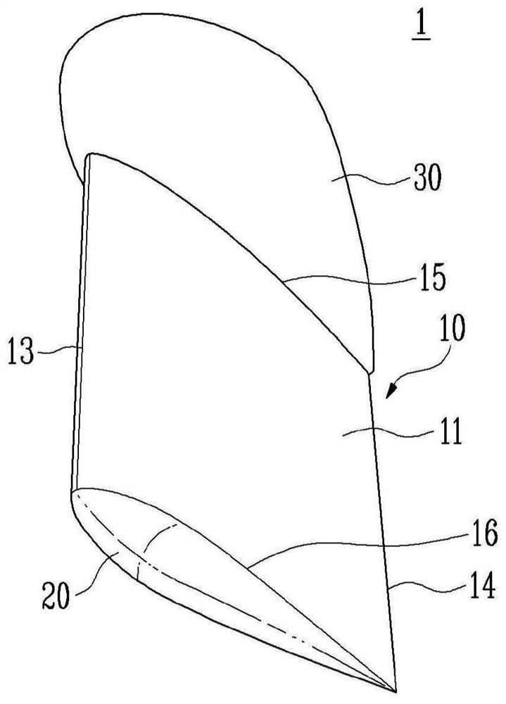
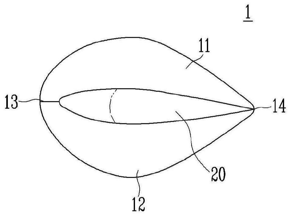
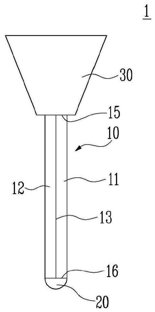
[0091] Figure 1A It is a lower perspective view of the rudder for ships of the present invention, Figure 1B is a bottom view o...


PUM


Abstract

The rudder for a ship according to an embodiment of the present invention is characterized in that it includes a rudder body for steering the ship through the wake of the propeller, and when the lower end of the rudder body is viewed from the side, it has a downward direction. Convex curve shape.

Description

technical field [0001] The present invention relates to a rudder for ships. [0002] The present invention was derived from the research conducted as part of the industrial integration source technology development project by the Ministry of Knowledge Economy and the Korea Industrial Technology Evaluation Manager (Project specific number: 10040060; Project title: Improvement of resistance propulsion performance, different ships type of energy-saving add-ons and their application in real ships). Background technique [0003] Generally, a large ship moves forward by using a fluid flow generated when a propeller attached to the stern of the hull rotates. At this time, a rudder is attached to the rear of the propeller, and by turning the rudder left and right, the flow direction of the fluid is adjusted, and the navigation direction is changed. [0004] As described above, in order to achieve a certain speed by the rotation of the propeller, it is necessary to use fuel such as...

Claims


Application Information

Patent Timeline
Patent Type & Authority Patents(China)
IPC IPC(8): B63H25/38
CPCB63H25/38
Inventor 崔时勋韩明伦张俸准郑锡湖成荣宰李允模
Owner HYUNDAI HEAVY IND CO LTD
Why Eureka
Try Eureka