A rudder for ship

A technology for rudders and ships. It is applied in directions such as rudder steering and steering. It can solve the problems of no rudder flow research and the inability to effectively reduce cavitation, and achieve the effects of maximizing propulsion performance, improving propulsion performance, and improving durability.

Active Publication Date: 2018-01-05
HYUNDAI HEAVY IND CO LTD
View PDF10 Cites 1 Cited by
  • Summary
  • Abstract
  • Description
  • Claims
  • Application Information

AI Technical Summary

Problems solved by technology

[0014] As mentioned above, for the rudders of Patent Documents 3 and 4, although the above-mentioned part of the problem of cavitation has been solved by the shape of the lower part of the rudder, on

Method used


Image

  • A rudder for ship
  • A rudder for ship
  • A rudder for ship

Examples


Example Embodiment

[0089] The purpose, specific advantages and novel features of the present invention can be more clarified by the following detailed description and preferred embodiments related to the accompanying drawings. In this specification, reference numerals are given to the constituent elements of each figure, and it should be noted that even if the same constituent elements are shown in different drawings, the same reference numerals are given as much as possible. In addition, in the process of describing the present invention, if it is determined that the description of the related known technology unnecessarily confuses the gist of the present invention, the detailed description thereof will be omitted.

[0090] Hereinafter, preferred embodiments of the present invention will be described in detail with reference to the drawings.

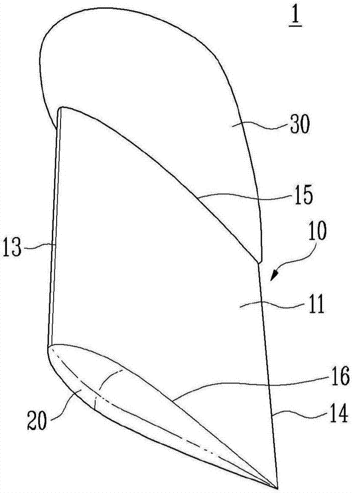
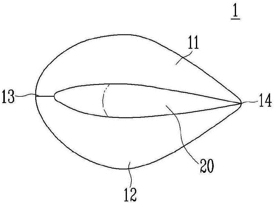
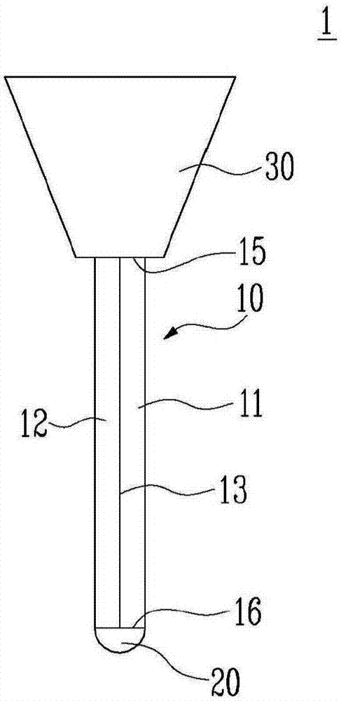
[0091] Figure 1A It is a bottom perspective view of the rudder for ships of the present invention, Figure 1B Is a bottom view of the rudder for ships of the...


PUM


Abstract

The embodiment of the invention relates to a rudder for a ship, and the rudder is characterized in that: the rudder comprises a rudder main body which controls the ship through wake flow of a propeller, when the lower side end of the rudder main body is observed from side, the rudder main body is in curve shape with downward projection.

Description

Technical field [0001] The present invention relates to a rudder for ships. [0002] The present invention is derived from research conducted as part of the industrial integration source technology development project, which is the Ministry of Knowledge Economy and the Korean Industrial Technology Evaluation Manager (Project inherent number: 10040060; project name: improvement of resistance propulsion performance, different ships The development of different types of energy-saving additional devices and their applications in actual ships). Background technique [0003] Generally, a large ship uses a fluid flow generated when a propeller installed at the stern of the ship rotates to move forward. At this time, a rudder is attached to the rear of the propeller, and the flow of the fluid is adjusted by turning the rudder to the left and right, thereby changing the navigation direction. [0004] As described above, in order to achieve a certain speed through the rotation of the propell...

Claims


Application Information

Patent Timeline
IPC IPC(8): B63H25/38
CPCB63H25/38
Inventor 崔时勋韩明伦张俸准郑锡湖成荣宰李允模
Owner HYUNDAI HEAVY IND CO LTD
Why Eureka
Try Eureka