Structural Assembly
A technology of structural components and components, applied in the direction of connecting components, aircraft parts, threaded fasteners, etc., can solve the problem of increasing the overall cost of aircraft manufacturing
Active Publication Date: 2018-01-05
THE BOEING CO
3 Cites 5 Cited by
AI-Extracted Technical Summary
Problems solved by technology
Therefore, various safety measures must be taken, whi...
Method used
[0026] A flange 140 may project outwardly from the body 130 of the inner bushing 104 proximate the second end portion 134 of the body 130. Flange 140 may be positioned in gap 30 between first member 12 and second member 14 and may include a first surface 142 adjoining inner side 15 of first member 12 and a second surface 142 adjoining outer side 17 of second member 14 . Two surfaces 144 . The second surfac...
Abstract
A structural assembly including a first member having an external side and an internal side, the first member defining a first member through-bore, a second member having an external side and an internal side, the second member defining a second member through-bore aligned with the first member through-bore, and a mechanical fastening system including a bushing at least partially received in the first member through-bore, the bushing defining a bushing through-bore and including a flange, wherein the flange is positioned in a gap between the internal side of the first member and the external side of the second member, a nut plate connected to the internal side of the second member, the nut plate defining a clearance bore aligned with the second member through-bore and the bushing through-bore, the nut plate including a nut, and a bolt extending through the bushing through-bore and into threaded engagement with the nut.
Application Domain
Engine sealsNuts +5
Technology Topic
EngineeringStructural component +2
Image
Examples
- Experimental program(1)
Example Embodiment
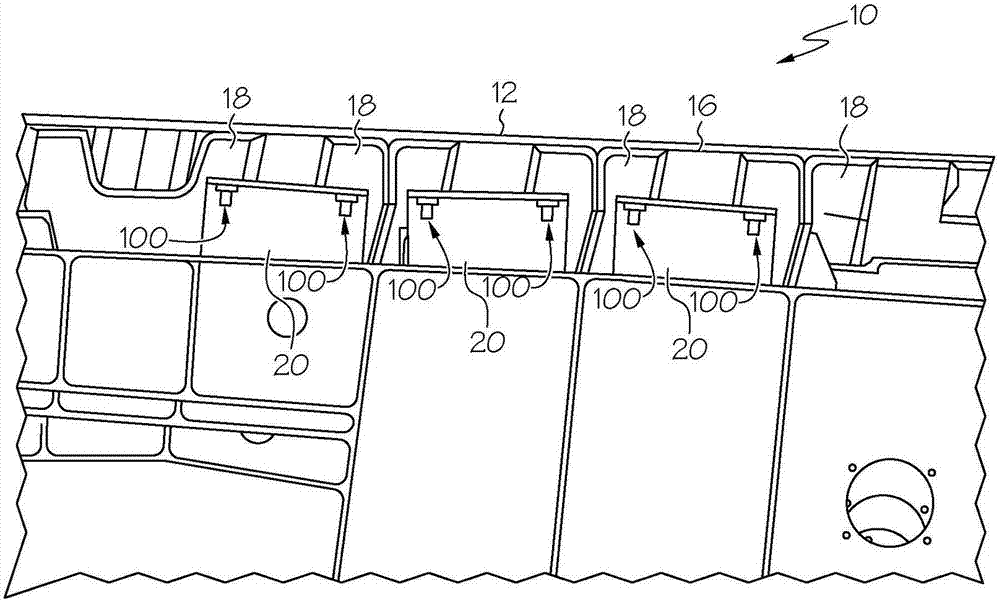
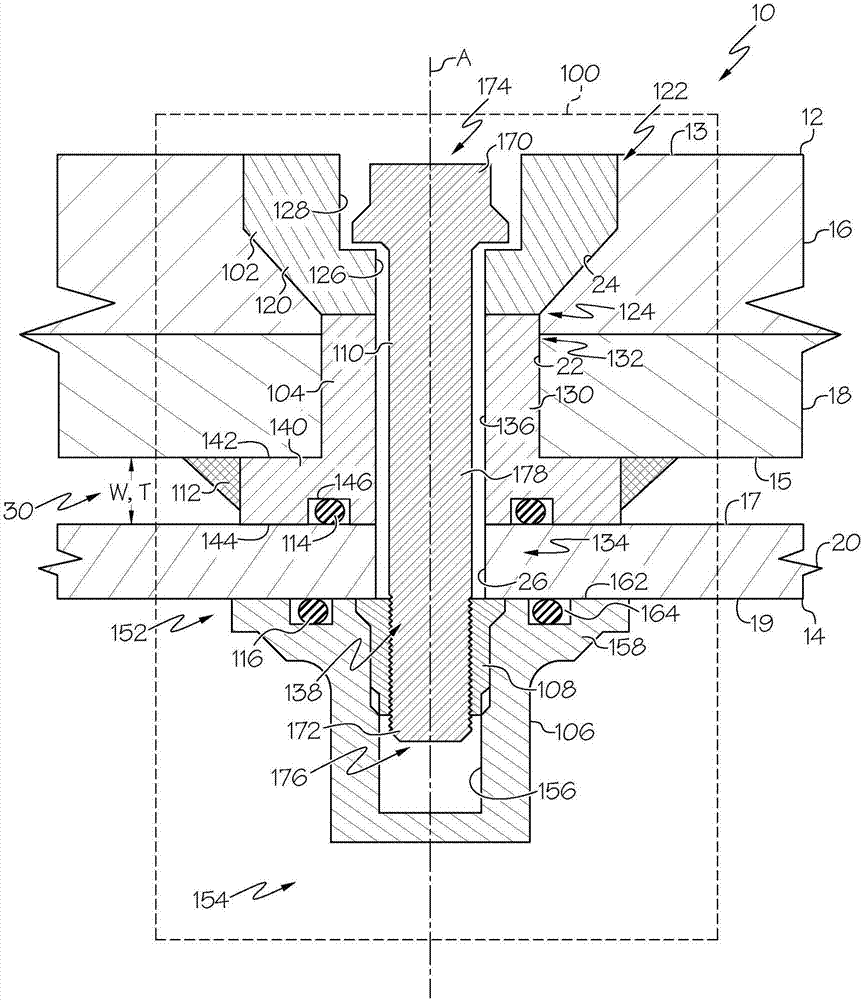
[0018] refer to figure 1 and figure 2 , a fluid-tight mechanical fastening system, generally designated 100, is disclosed, and a structural assembly, generally designated 10, comprising a connection to a second member using the disclosed fluid-tight mechanical fastening system 100 14 of the first member 12 . As described in greater detail herein, the disclosed fluid-tight mechanical fastening system 100 may facilitate externally connecting the first member 12 to the second member 14 (from the outer side 13 ( figure 2 )) while maintaining the fluid-tightness of the first member 12 .
[0019] In one specific application, the disclosed structural assembly 10 may be the wing of an aircraft, such as a passenger or commercial aircraft. Accordingly, the first member 12 of the structural assembly 10 may include aircraft wing skin panels 16 and optionally stringers 18 connected to the skin panels 16 , while the second member 14 of the structural assembly 10 may include spar ribs 20 . However, those skilled in the art will appreciate that various components may be joined together using the disclosed fluid-tight mechanical fastening system 100, whether for aerospace applications or non- Aerospace applications.
[0020] reference now figure 2 , the first member 12 of the structural assembly 10 may define a first member through hole 22 , and the first member through hole 22 may include a countersunk hole 24 . The second member 14 of the structural assembly 10 may define a second member through hole 26 . The first member through hole 22 may be aligned with the second member through hole 26 along the through hole axis A. As shown in FIG. The disclosed fluid-tight mechanical fastening system 100 may extend through the first member through hole 22 and the second member through hole 26 to connect the first member 12 to the second member 14 .
[0021] The disclosed fluid-tight mechanical fastening system 100 may include an outer bushing 102 , an inner bushing 104 , a nut piece 106 , a nut 108 , and a bolt 110 . Additional components and features may be included in the disclosed fluid-tight mechanical fastening system 100 without departing from the scope of the present disclosure. For example, in particular embodiments, the disclosed fluid-tight mechanical fastening system 100 may further include a first seal 112 (eg, a fillet seal) between the first member 12 and the inner bushing 104 seal, fillet seal)), a second seal 114 (eg, an O-ring) between the inner bushing 104 and the second member 14 , and/or between the second member 14 and the nut piece 106 the third seal 116 (eg, O-ring).
[0022] The outer bushing 102 of the disclosed fluid-tight mechanical fastening system 100 may include a body 120 sized and shaped to be tightly received in the first member through hole of the first member 12 of the structural assembly 10 Inside and near (at or near) the outer side 13 of the first member 12 . For example, the body 120 of the outer bushing 102 may be sized and shaped to be tightly received within the counterbore 24 of the first member through hole 22 of the first member 12 . The body 120 of the outer bushing 102 may include a first end portion 122 and a second end portion 124 axially opposite the first end portion 122 (with respect to the through hole axis A). The body 120 of the outer bushing 102 may define an outer bushing through hole 126 extending axially from the first end portion 122 to the second end portion 124 . The outer bushing through hole 126 may include a countersunk hole 128 proximate the first end portion 122 of the body 120 of the outer bushing 102 .
[0023] The body 120 of the outer bushing 102 may be formed from various materials, including combinations of materials, without departing from the scope of the present disclosure. In the event of a lightning strike, forming the body 120 of the outer bushing 102 from a conductive material may facilitate dissipation of charge to the surrounding first member 12 . The strength and stiffness of the material forming the body 120 of the outer bushing 102 may also be a consideration, as the bolts 110 may directly contact the outer bushing 102 . In one particular configuration, the body 120 of the outer bushing 102 may be formed from a metallic material (eg, a metal or metal alloy). As a specific, non-limiting example, the body 120 of the outer bushing 102 may be formed from a titanium alloy such as an aerospace-grade titanium alloy (eg, Ti-6Al-4V or Ti-5Al-2.5Sn). However, the use of non-metallic materials such as polymers and composite materials (eg, carbon fiber reinforced plastics) is also contemplated.
[0024] The inner bushing 104 of the disclosed fluid-tight mechanical fastening system 100 may include a body 130 sized and shaped to be tightly received in the first member through-hole of the first member 12 of the structural assembly 10 22 and near the inner side 15 of the first member 12 . The body 130 of the inner bushing 104 may include a first end portion 132 and a second end portion 134 axially opposite (with respect to the through hole axis A) of the first end portion 132 . The body 130 of the inner bushing 104 may define an inner bushing through hole 136 extending axially from the first end portion 132 to the second end portion 134 .
[0025] Thus, in figure 2 In the assembled configuration shown, the first end portion 132 of the inner bushing 104 may abut the second end portion 124 of the outer bushing 102 . Further, in the assembled configuration, the outer bushing through holes 126 may be axially aligned with the inner bushing through holes 136 , and the inner bushing through holes may be axially aligned with the second member through holes 26 of the second member 14 , Bolt receiving holes 138 including outer bushing through holes 126 , inner bushing through holes 136 , second member through holes 26 and clearance holes 156 of nut piece 106 are thereby defined.
[0026]The flange 140 may protrude outwardly from the body 130 of the inner bushing 104 proximate the second end portion 134 of the body 130 . The flange 140 may be positioned in the gap 30 between the first member 12 and the second member 14 and may include a first surface 142 adjacent the inner side 15 of the first member 12 and a first surface 142 adjacent the outer side 17 of the second member 14 . Two surfaces 144 . The second surface 144 of the flange 140 may be axially opposite (with respect to the through hole axis A) the first surface 142, thereby defining a flange thickness T therebetween. The flange thickness T may be substantially equal to the width W of the gap 30 between the first member 12 and the second member 14 , thereby potentially eliminating the need for a spacer to be placed between the first member 12 and the second member 14 .
[0027] The first seal 112 may seal the interface between the inner side 15 of the first member 12 and the flange 140 of the inner liner 104, thereby inhibiting, if not absolutely preventing, fluid from passing through the interface. For example, the first seal 112 may be a chamfered seal extending circumferentially around the flange 140 of the inner bushing 104 . For example, the first seal 112 may be formed of (or may include) a polysulfide-based interface sealant material. Other techniques may also be used to seal the interface between the inner side 15 of the first member 12 and the flange 140 of the inner bushing 104 .
[0028] The second surface 144 of the flange 140 of the inner bushing 104 may define a circumferential groove 146 . The second seal 114 , which may be an O-ring or the like, may be received in the groove 146 . The second seal 114 may seal the interface between the inner bushing 104 and the second member 14 when the second surface 144 of the flange 140 of the inner bushing 104 abuts the outer side 17 of the second member 14 . Accordingly, the flange 140 of the inner bushing 104 may be in sealing engagement with the outer side 17 of the second member 14 .
[0029] The body 130 of the inner liner 104 may be formed of various materials including combinations of materials without departing from the scope of the present disclosure. In one particular construction, the body 130 of the inner liner 104 may be formed from a polymeric material. As a specific non-limiting example, the body 130 of the inner liner 104 may be formed from a dielectric thermoplastic polymer such as polyetheretherketone (PEEK). However, other materials are also contemplated, such as composite materials and metallic materials.
[0030] The nut sheet 106 of the disclosed fluid-tight mechanical fastening system 100 may include a body 150 having a first end portion 152 and a shaft axially opposite (with respect to the through-hole axis A) of the first end portion 152 . The second end portion 154 . The body 150 of the nut piece 106 may define a clearance hole 156 extending from the first end portion 152 toward (but not completely through) the second end portion 154 . The flange 158 may project outwardly from the body 150 of the nut piece 106 proximate the first end portion 152 of the body 150 .
[0031] The nut 108 may be received (eg, press fit) in the clearance hole 156 of the nut piece 106 proximate the first end portion 152 of the body 150 of the nut piece 106 . The nut 108 is engageable with the nut piece 106 such that the nut 108 does not rotate about the through hole axis A relative to the nut piece 106 . For example, the nut 108 may have a hexagonal cross-sectional profile, and the clearance hole 156 of the nut sheet 106 may have a corresponding hexagonal shape.
[0032] like figure 2 As shown, the nut piece 106 and the nut 108 may be two separate components. However, in one variation, the nut 108 may be integral with the nut piece 106 (ie, the nut 108 and the nut piece 106 may be formed as a single unit).
[0033] The nut piece 106 and the nut 108 may be the same or different in composition. In one particular configuration, the nut piece 106 may be formed from a polymeric material, and the nut 108 may be formed from a metallic material (eg, a metal or metal alloy). As a specific, non-limiting example, the nut sheet 106 may be formed of a dielectric thermoplastic polymer such as polyetheretherketone (PEEK), while the nut 108 may be formed of an alloy such as aerospace grade titanium (eg, Ti-6Al-4V or Ti- 5Al-2.5Sn) titanium alloy formation.
[0034] The nut piece 106 may be attached to the second member 14 such that the nut 108 and clearance hole 156 are axially aligned with the outer bushing through hole 126 , the inner bushing through hole 136 and the second member through hole 26 . Various techniques may be used to connect the nut piece 106 to the second member 14 . For example, as image 3 As shown, a mechanical fastener 160 (eg, rivet, screw, bolt, etc.) may be inserted through the flange 158 of the nut piece 106 and engaged with the adjacent second member 14 to connect the nut piece 106 to the The second member 14 .
[0035] re-reference figure 2 , the mating surface 162 of the flange 158 of the nut piece 106 may define a circumferential groove 164 . The third seal 116 , which may be an O-ring or the like, may be received in the groove 164 . The third seal 116 may seal the interface between the second member 14 and the nut piece 106 when the mating surface 162 of the flange 158 of the nut piece 106 abuts the inner side 19 of the second member 14 . Accordingly, the flange 158 of the nut piece 106 may be in sealing engagement with the inner side 19 of the second member 14 .
[0036] The bolt 110 of the disclosed fluid-tight mechanical fastening system 100 may include a head 170 and a threaded portion 172 disposed at opposite ends 174 , 176 of the shaft 178 . The shaft 178 of the bolt 110 can extend through the bolt receiving hole 138 defined by the outer bushing through hole 126 , the inner bushing through hole 136 , the second member through hole 26 and the clearance hole 156 such that the threaded portion 172 of the bolt 110 can be threaded. Threaded into engagement with nut 108 . When the threaded portion 172 of the bolt 110 is threaded into engagement with the nut 108 , the head 170 of the bolt 110 may be received in the countersunk hole 128 of the outer bushing through hole 126 of the outer bushing 102 and may abut the outer bushing 102 .
[0037] The bolt 110 may be formed from various materials including combinations of various materials without departing from the scope of the present disclosure. It is contemplated that the bolt 110 may be formed from the same material as the nut 108 . In one particular configuration, the bolt 110 may be formed from a metallic material (eg, a metal or metal alloy). As a specific, non-limiting example, the bolt 110 may be formed from a titanium alloy such as an aerospace-grade titanium alloy (eg, Ti-6Al-4V or Ti-5Al-2.5Sn). However, the use of other materials, such as composite materials, is also contemplated.
[0038] reference now Figures 4A-4D , showing the steps of the disclosed method for use with the disclosed fluid-tight mechanical fastening system 100 ( figure 2 ) to assemble the structural assembly 10 ( figure 2 ). Additional steps are also contemplated, such as fabrication of the components of the disclosed fluid-tight mechanical fastening system 100 (eg, outer bushing 102, inner bushing 104, nut sheet 106, nut 108, and bolt 110).
[0039] like Figure 4A As shown, a first member 12 and a second member 14 may be provided. First member through holes 22 , which may include countersunk holes 24 , may be formed in the first member 12 . Second member through holes 26 may be formed in the second member 14 . For example, the first member through holes 22 and the second member through holes 26 may be formed by machining/drilling the first member 12 and the second member 14 using suitable tools.
[0040] like Figure 4B As shown, the disclosed fluid-tight mechanical fastening system 100 ( figure 2 ) is inserted into the first member through hole 22 such that the outer sleeve 102 is seated in the countersunk hole 24 of the first member through hole 22 . Additionally, the inner bushing 104 may be inserted into the first member through hole 22 such that the flange 140 abuts the inner side 15 of the first member 12 . With outer bushing 102 and inner bushing 104 inserted, outer bushing through hole 126 may be aligned with inner bushing through hole 136 and first end portion 132 of inner bushing 104 may abut outer bushing 102 of the second end portion 124.
[0041] still refer to Figure 4B , the nut piece 106 (including the nut 108 and the third seal 116 ) can be attached to the inner side 19 of the second member 14 such that the nut 108 and clearance hole 156 are connected to the second member through hole defined by the second member 14 26 Alignment. like image 3 As shown, the connection between the nut piece 106 and the second member 14 may be formed, for example, using a mechanical fastener 160 inserted through the flange 158 of the nut piece 106 and engaged with the second member 14 . The connection between the nut piece 106 and the second member 14 may compress the third seal 116 between the nut piece 106 and the inner side 19 of the second member 14 .
[0042] still refer to Figure 4B , the thickness T of the flange 140 of the inner bushing 104 ( figure 2 ) may initially be larger than desired. Accordingly, flange 140 may optionally be cut along line L, such as with a saw or similar tool, to provide desired flange 140 of inner bushing 104 before proceeding to the next step of the disclosed assembly method thickness T. The desired thickness T and thus the location of the line L may depend on the gap 30 ( figure 2 )the size of.
[0043] like Figure 4C As shown, once the flange 140 of the inner bushing 104 has optionally been trimmed to size (eg, along the Figure 4B Line L) shown, then the first seal 112 and the second seal 114 can be introduced. The first seal 112 may be introduced by applying a sealant material as a fillet around the perimeter between the flange 140 of the inner liner 104 and the inner side 15 of the first member 12 to extend. By cutting a groove 146 in the second surface 144 of the flange 140, and inserting a second seal 114 (eg, an O-ring) into the cut groove 146, a second seal, which may be an O-ring or the like, may be introduced Seal 114 .
[0044] like Figure 4D As shown, the first member 12 can interact with the second member 14 using the outer bushing 102 and inner bushing 104 assembled on the first member 12 and the nut plate 106 and nut 108 assembled on the second member 14 approach so as to align the outer bushing through hole 126 and the inner bushing through hole 136 with the second member through hole 26 and the clearance hole 156 to define the bolt receiving hole 138 . Bolts 110 may then be introduced from the outer side 13 of the first member 12, through the bolt receiving holes 138, and finally (see figure 2 ) is threaded into engagement with the nut 108 to form a figure 2 Structural assembly 10 is shown.
[0045] Therefore, if figure 2 As shown, the second seal 114 may be compressed between the inner bushing 104 and the outer side 17 of the second member 14 when the bolt 110 is fully threaded into engagement with the nut 108 . Accordingly, the bolt receiving holes 138 may be isolated from any fluid (eg, jet fuel) on the inner side 15 of the first member 12 .
[0046] refer to Figure 5 , an alternate embodiment of the disclosed fluid-tight mechanical fastening system generally designated 200 may include a bushing 203 , a nut piece 206 , a nut 208 and a bolt 210 . The disclosed fluid-tight mechanical fastening system 200 may also include a first seal 212 (eg, a chamfer seal) between the first member 12' and the bushing 203, between the bushing 203 and the second member A second seal 214 (eg, an O-ring) between the second member 14 ′ and/or a third seal 216 (eg, an O-ring) between the second member 14 ′ and the nut piece 206 .
[0047] System 200 may be substantially the same as system 100 , except that a single bushing 203 replaces outer bushing 102 and inner bushing 104 of system 100 .
[0048]Bushing 203 may be formed of various materials including combinations of materials without departing from the scope of the present disclosure. Flexibility (during insertion of the bushing 203 into the first member 12') may be a material selection consideration. In one particular construction, the bushing 203 may be formed from a polymeric material. As a specific non-limiting example, the bushing 203 may be formed of a dielectric thermoplastic polymer such as polyetheretherketone (PEEK). However, other materials are also contemplated, such as composite materials and metallic materials.
[0049] available in as Image 6 The aircraft manufacturing and maintenance method 400 is shown as well as in Figure 7 Examples of the present disclosure are described in the context of aircraft 402 shown. During pre-production, aircraft manufacturing and maintenance method 400 may include specification and design 404 of aircraft 402 and material procurement 406 . During production, component/subassembly manufacturing 408 and system integration 410 of aircraft 402 occur. Thereafter, aircraft 402 may be certified and delivered 412 for entry into service 414 . While in use by a customer, aircraft 402 is scheduled for routine repair and maintenance 416, which may also include modification, reconfiguration, refurbishment, and the like.
[0050] Each of the processes of method 400 may be performed or performed by a system integrator, a third party, and/or an operator (eg, a customer). For the purposes of this description, system integrators may include, but are not limited to, any number of aircraft manufacturers and primary system subcontractors; third parties may include, but are not limited to, any number of sellers, subcontractors, and suppliers; and operators may Are airlines, leasing companies, military entities, service agencies, etc.
[0051] like Figure 7 As shown, aircraft 402 produced by example method 400 may include fuselage 418 and interior 422 having a plurality of systems 420 . Examples of number of systems 420 may include one or more of propulsion system 424 , electrical system 426 , hydraulic system 428 , and environmental system 430 . Any number of other systems may be included.
[0052] The disclosed fluid-tight mechanical fastening system may be employed during any one or more of the stages of aircraft manufacturing and maintenance method 400 . As one example, the disclosed fluid-tight mechanical fastening system may be used during material procurement 406 . As another example, components or subassemblies corresponding to component/subassembly manufacturing 408 , system integration 410 , and/or repair and maintenance 416 may be produced or manufactured using the disclosed fluid-tight mechanical fastening systems. As another example, the fuselage 418 and/or the interior 422 may be constructed using the disclosed fluid-tight mechanical fastening system. Also, one or more device instances may be utilized during component/subassembly manufacturing 408 and/or system integration 410, for example, by substantially accelerating or reducing the cost of assembly of aircraft 402, such as fuselage 418 and/or interior 422 , method examples, or a combination thereof. Similarly, while aircraft 402 is in service, one or more of the system examples, method examples, or combinations thereof may be utilized, such as, but not limited to, for repair and maintenance 416 .
[0053] Furthermore, the present disclosure includes embodiments in accordance with the following terms:
[0054] Clause 1. A structural assembly 10 comprising:
[0055] the first member 12, including the outer side 13 and the inner side 15, the first member defines the first member through hole 22;
[0056] a second member 14, including an outer side 17 and an inner side 19, the second member 14 defining a second member through hole 26 aligned with the first member through hole 22; and
[0057] Mechanical fastening system 100, including:
[0058] A bushing 104 , at least partially received in the first member through hole 22 , the bushing 104 defines a bushing through hole 136 and includes a flange 140 , wherein the flange 140 is positioned at the first in the gap 30 between the inner side 15 of the member 12 and the outer side 17 of the second member 14;
[0059] a nut piece 106, attached to the inner side 19 of the second member 14, the nut piece 106 defining a clearance hole 156 aligned with the second member through hole 26 and the bushing through hole 136, the nut piece 106 includes a nut 108; and
[0060] A bolt 110 extends through the bushing through hole 136 and is threadedly engaged with the nut 108 .
[0061] Clause 2. The structural assembly 10 of clause 1, further comprising a first seal 112 sealing an interface between the flange 140 and the inner side 15 of the first member 12.
[0062] Clause 3. The structural assembly 10 of clause 2, wherein the first seal 112 comprises a chamfered seal.
[0063] Clause 4. The structural assembly 10 of clause 1 , further comprising a second seal 114 positioned between the flange 140 and the outer side 17 of the second member 14 .
[0064] Clause 5. The structural assembly 10 of clause 4, wherein the second seal 114 includes an O-ring, and wherein the O-ring is received in a groove 146 formed in the bushing 104 middle.
[0065] Clause 6. The structural assembly 10 of clause 1, further comprising a third seal 116 positioned between the nut sheet 106 and the inner side 19 of the second member 14.
[0066] Clause 7. The structural assembly 10 of clause 6, wherein the third seal 116 includes an O-ring, and wherein the O-ring is received in a groove formed in the nut piece 106 164 in.
[0067] Clause 8. The structural assembly 10 of Clause 1, further comprising an outer bushing 102 at least partially received in the first member through hole 22, the outer bushing 102 defining an overall connection with the bushing 104 The bushing through holes 136 are aligned with the outer bushing through holes 126 .
[0068] Clause 9. The structural assembly 10 of Clause 8, wherein the first member through hole 22 includes a countersunk hole 24, and wherein the outer bushing 102 is seated in the countersunk hole 24.
[0069] Clause 10. The structural assembly 10 of Clause 8, wherein the outer bushing 102 is formed of a metallic material.
[0070] Clause 11. The structural assembly 10 of clause 10, wherein the bushing 104 and the nut sheet 106 are formed of a polymeric material.
[0071] Clause 12. The structural assembly 10 of Clause 1, wherein the nut 108 is press fit into the clearance hole 156.
[0072] Clause 13. The structural assembly 10 of clause 1, wherein the nut piece 106 is connected to the inner side 19 of the second member 14 by mechanical fasteners 160.
[0073] Clause 14. An aircraft comprising the structural assembly of clause 1.
[0074] Clause 15. The aircraft of clause 14, wherein the first member comprises an aircraft wing skin panel and the second member comprises a rib.
[0075] Clause 16. A structural component comprising:
[0076] a first member including an outer side and an inner side, the first member defining a first member through hole;
[0077] a second member including an outer side and an inner side, the second member defining a second member through hole aligned with the first member through hole; and
[0078] Mechanical fastening systems, including:
[0079] an outer bushing at least partially received in the first member through hole and proximate the outer side of the first member, the outer bushing defining an outer bushing through hole;
[0080] an inner bushing at least partially received in the first member through hole and proximate the inner side of the first member, the inner bushing defining an inner bushing through hole, and including a position positioned on the first member a flange in the gap between the inner side of the second member and the outer side of the second member, wherein the flange is in sealing engagement with the outer side of the second member;
[0081] a chamfer seal sealing the interface between the flange and the inner side of the first member;
[0082] a nut piece in sealing engagement with the inner side of the second member, the nut piece defining a clearance hole and including a nut received in the clearance hole; and
[0083] A bolt extends through the outer bushing through hole and the inner bushing through hole and is threadedly engaged with the nut.
[0084] Clause 17. The structural assembly of clause 16, wherein the outer bushing is formed of a metallic material and the inner bushing is formed of a polymeric material.
[0085] Clause 18. A method for assembling a first member and a second member, comprising:
[0086] forming a first member through hole in the first member and forming a second member through hole in the second member;
[0087] inserting a bushing into the first member through hole, the bushing defining a bushing through hole and including a flange, wherein the flange abuts the inner side of the first member;
[0088] connecting a nut piece to the inner side of the second member, wherein the nut piece defines a clearance hole aligned with the second member through hole and includes a nut received in the clearance hole;
[0089] aligning the bushing through hole with the second member through hole; and
[0090] A bolt is inserted through the bushing through hole, and the bolt is screwed into engagement with the nut.
[0091] Clause 19. The method of clause 18, further comprising:
[0092] applying a first seal to the interface between the flange and the inner side of the first member;
[0093] applying a second seal to the flange such that the second seal seals the interface between the flange and the outside of the second member; and
[0094] A third seal is applied to the nut piece such that the third seal seals the interface between the nut piece and the inner side of the second member.
[0095] Clause 20. The method of clause 18, further comprising trimming the flange prior to the step of inserting the bolt.
[0096] The disclosed fluid-tight mechanical fastening system and related structural components are described in the context of an aircraft; however, those of ordinary skill in the art will readily recognize that the disclosed fluid-tight mechanical fastening system and related structural components are The Structural Components are available for a variety of vehicle as well as non-vehicle applications. For example, implementations of the embodiments described herein may be implemented in any type of vehicle including, for example, helicopters, passenger ships, automobiles, and the like.
[0097]While various embodiments of the disclosed fluid-tight mechanical fastening system and associated structural components have been shown and described, modifications may occur to those skilled in the art upon reading the specification. This application includes such modifications, and is limited only by the scope of the claims.
PUM


Description & Claims & Application Information
We can also present the details of the Description, Claims and Application information to help users get a comprehensive understanding of the technical details of the patent, such as background art, summary of invention, brief description of drawings, description of embodiments, and other original content. On the other hand, users can also determine the specific scope of protection of the technology through the list of claims; as well as understand the changes in the life cycle of the technology with the presentation of the patent timeline. Login to view more.