

Common mode choke
A common mode choke coil and coil conductor technology, applied in the direction of transformer/inductor coil/winding/connection, inductor, printed inductor, etc., can solve the problem of different coupling between wires
- Summary
- Abstract
- Description
- Claims
- Application Information
AI Technical Summary
Problems solved by technology
Method used
Image

Examples
Embodiment 1
[0037] refer to Figure 1 ~ Figure 3C The drawings of the drawings illustrate the common mode choke coil according to Embodiment 1.
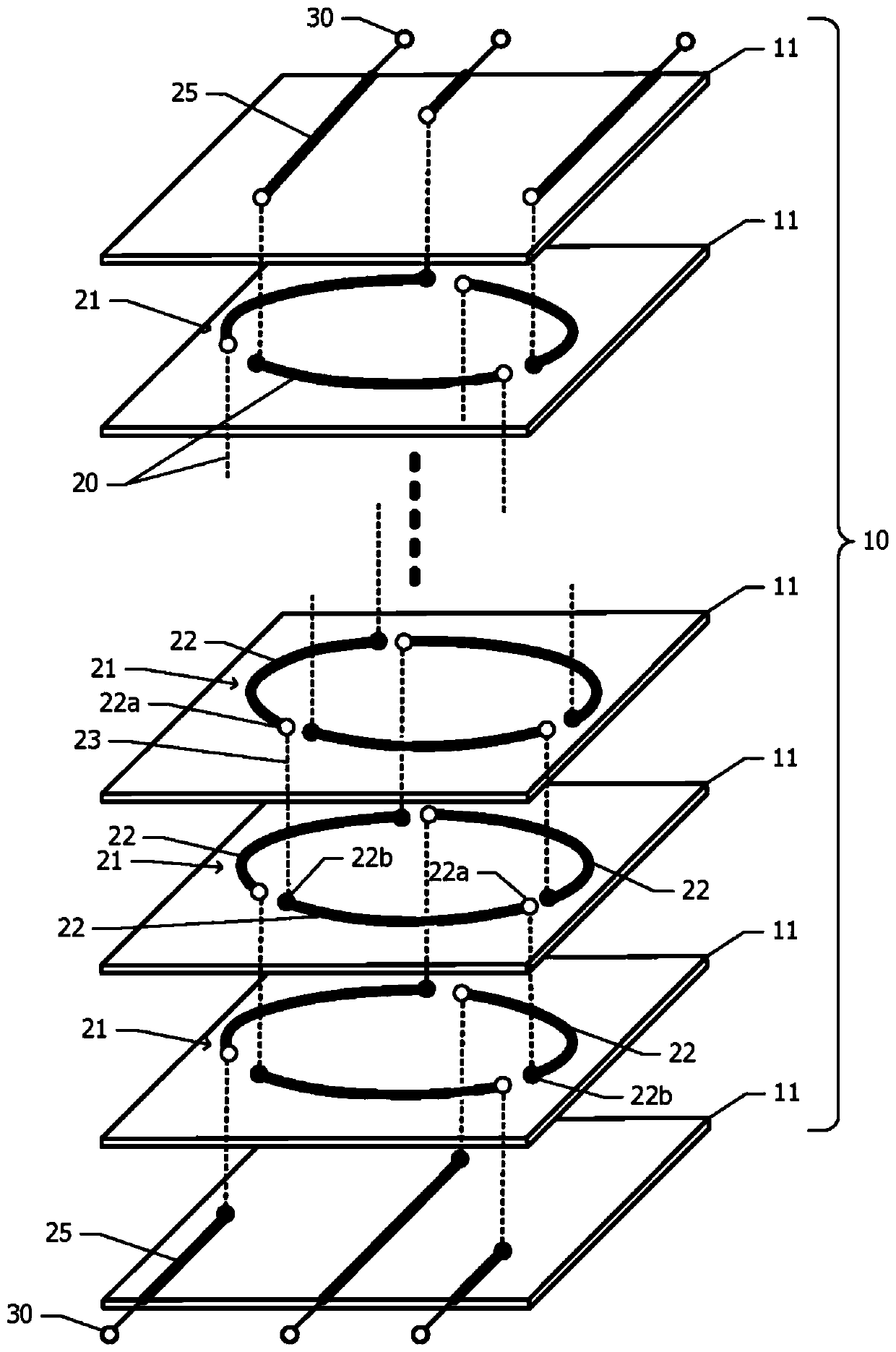
[0038] figure 1 A schematic exploded perspective view showing the common mode choke coil according to Embodiment 1. The common mode choke coil according to Embodiment 1 has an insulating member 10 composed of a plurality of insulating layers 11, a plurality of, for example, three inductors 20 arranged inside the insulating member 10, and each of the plurality of inductors 20 A plurality of external electrodes 30 are respectively connected to both ends of one inductor 20 . The insulating layer 11 is formed by, for example, firing a green sheet or glass paste containing ferrite powder.
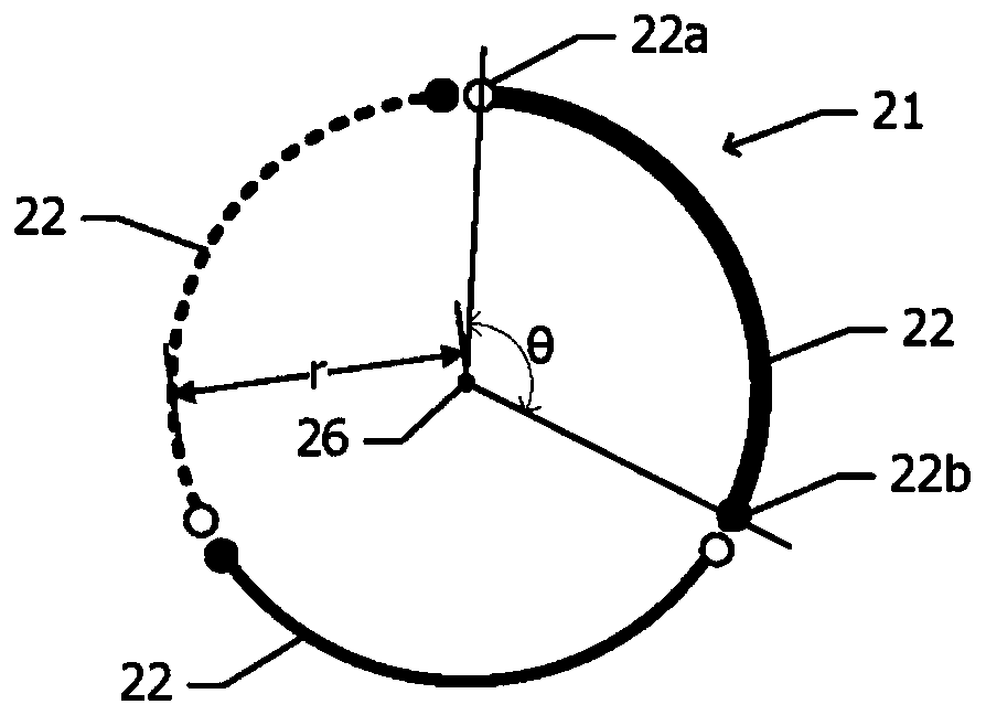
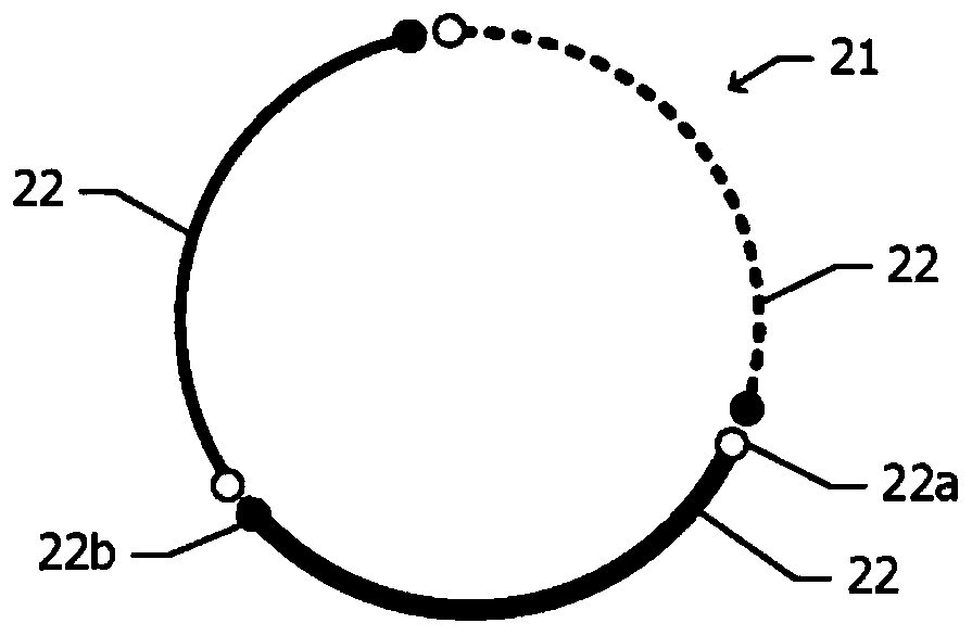
[0039] A plurality of coil conductor layers 21 stacked in the first direction (lamination direction) are arranged inside the insulating member 10 . For example, the coil conductor layers 21 are arranged on the interfaces of the two insulating layers 11 adjacen...
Embodiment 2
[0058] refer to Figure 4A ~ Figure 4C The drawings of the drawings illustrate the common mode choke coil according to the second embodiment. Hereinafter, differences from Embodiment 1 will be described, and descriptions of common structures will be omitted. In Example 1, the coil conductor 22 included in the coil conductor layer 21 has a planar shape along the circumference, but in Example 2, the coil conductor 22 has a planar shape along the outer periphery of an equilateral triangle.
[0059] Figure 4A , Figure 4B , Figure 4C The plan views of the coil conductor layers 21 of the first layer, the second layer, and the third layer of the common mode choke coil according to the second embodiment are respectively shown. In any layer, the coil conductor 22 has a shape along the outer periphery of a regular triangle. The coil conductor 22 is curved at a position corresponding to the vertices of the equilateral triangle. The pattern constituted by the three coil conductor...
Embodiment 3
[0063] refer to Figure 5A ~ Figure 5C The drawing of the drawing explains the common mode choke coil according to the third embodiment. Hereinafter, differences from Embodiment 1 will be described, and descriptions of common structures will be omitted. In Embodiment 1, the common mode choke coil includes three inductors 20 , but in Embodiment 3, four inductors 20 are included.
[0064] Figure 5A , Figure 5B , Figure 5C The plan views of the coil conductor layers 21 of the first layer, the second layer, and the third layer of the common mode choke coil according to the third embodiment are respectively shown. Each of the coil conductor layers 21 includes four coil conductors 22 . Represent the coil conductor 22 of the first inductor 20 with the thick solid line, represent the coil conductor 22 of the second inductor 20 with the thick dashed line, represent the coil conductor 22 of the 3rd inductor 20 with the thin solid line, represent the coil conductor 22 of the 3rd ...
PUM
 Abstract
Description
Claims
Application Information