

Workpiece storage method
A storage method and technology for workpieces, which are applied in the directions of sending objects, processing thin materials, stacking objects, etc., can solve problems such as inability to store 100 workpieces.
- Summary
- Abstract
- Description
- Claims
- Application Information
AI Technical Summary
Problems solved by technology
Method used
Image

Examples
no. 1 Embodiment approach
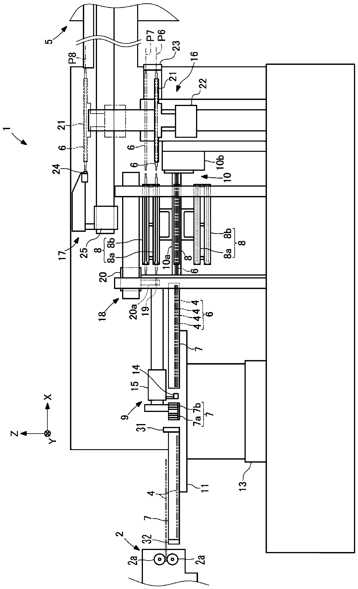
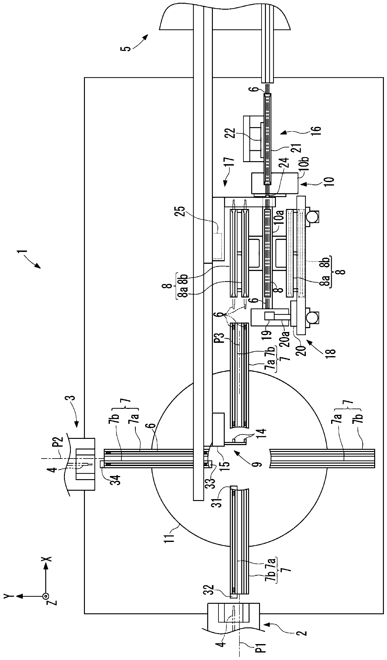
[0029] Such as figure 1 and figure 2 As shown, the wire lug supply apparatus 1 receives the wire lug 4 (workpiece) sent out by two lead lug manufacturing apparatuses 2 and 3, and supplies it to the molding apparatus 5. The lead sheet manufacturing apparatus 2 includes a pair of upper and lower conveying rollers 2 a that sandwich the lead sheet 4 . Similarly, the lead sheet manufacturing apparatus 3 includes a pair of upper and lower conveying rollers 3a for sandwiching the lead sheet 4 (see Figure 6 ).
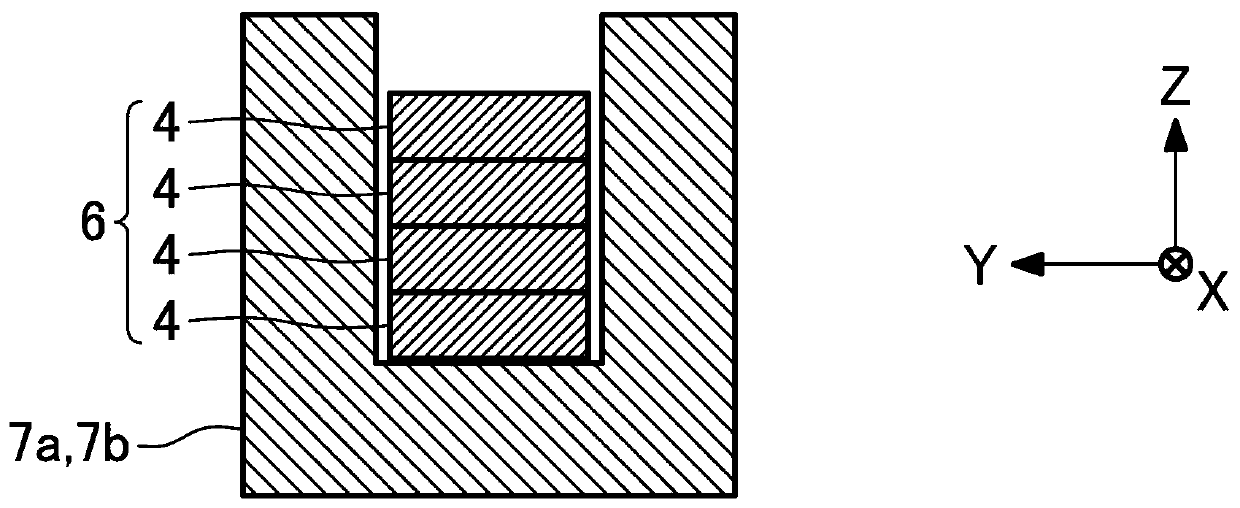
[0030] The lead sheet 4 is manufactured by cutting the insulating-coated rectangular wire into predetermined lengths in the lead sheet manufacturing apparatuses 2 and 3 . Therefore, the cross section of the lead sheet 4 is rectangular, and has two faces on the long side and two faces on the short side. The direction perpendicular to the two surfaces on the long side is the thickness direction of the lead sheet 4 , and the direction perpendicular to the two surfaces on t...
no. 2 Embodiment approach
[0081] In the second embodiment shown in FIG. 8 , the first contact detection sensor 41 is not provided. The storage control unit 40 controls the air to be continuously ejected from the first air nozzle 36 . In addition, the same code|symbol is attached|subjected to the same component as the above-mentioned embodiment, and the detailed description is abbreviate|omitted.
[0082] like Figure 8A As shown, the storage control unit 40 performs control such that the first air nozzle 36 keeps blowing out air even in the state before the lead piece 4 comes into contact with the first end plate 31 .
[0083] The lead sheet manufacturing apparatus 2 includes a pair of upper and lower conveyance rollers 2a, and a backup roller 2b for supporting the upper surface of the lead sheet 4 at the upstream side in the conveyance direction of the lead sheet 4 than the conveyance roller 2a. . In addition, it is not limited to a rotating member such as a support roller, and for example, a slida...
no. 3 Embodiment approach
[0088] In the third embodiment shown in FIG. 9 , the first air nozzle 36 blows air upward. In addition, the same code|symbol is attached|subjected to the same component as the above-mentioned embodiment, and the detailed description is abbreviate|omitted.
[0089] like Figure 9A As shown, the first air nozzle 36 is located below the first storage tank 7 and is arranged on the front end side. An air hole 7c through which the air jetted from the first air nozzle 36 passes is formed in the first storage recess 7a of the first storage tank 7 . The air injected from the first air nozzle 36 passes through the air hole 7c and is injected upward.
[0090] like Figure 9B As shown, when the lead piece 4 is in contact with the first end plate 31 , the first contact detection sensor 41 detects the contact of the lead piece 4 and sends a contact detection signal to the storage control unit 40 .
[0091] The storage control unit 40 drives the air supply device 38 in response to receiv...
PUM
 Abstract
Description
Claims
Application Information