A hoisting tool for propeller blades

A hoisting and tooling technology, which is applied in the field of hoisting and hoisting of blades, can solve the problem that the blades are not easy to be hoisted, and achieve the effect of achieving balanced, stable and balanced hoisting.

Active Publication Date: 2019-07-26
WUHAN MARINE MACHINERY PLANT
View PDF6 Cites 0 Cited by
  • Summary
  • Abstract
  • Description
  • Claims
  • Application Information

AI Technical Summary

Problems solved by technology

[0004] In order to solve the problem that the blade is not easy to hoist, the embodiment of the present invention provides a hoisting tool for the blade

Method used


Image

  • A hoisting tool for propeller blades
  • A hoisting tool for propeller blades
  • A hoisting tool for propeller blades

Examples


Embodiment

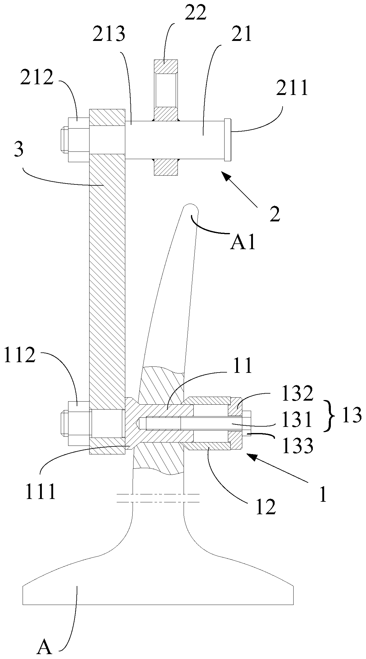
[0029] An embodiment of the present invention provides a hoisting tool for a blade. A hoisting hole is pre-opened on the blade, and the hoisting hole is used to cooperate with the hoisting tool. Such as figure 1 As shown, the hoisting tool includes a mounting part 1 , a hoisting part 2 and a connecting arm 3 .

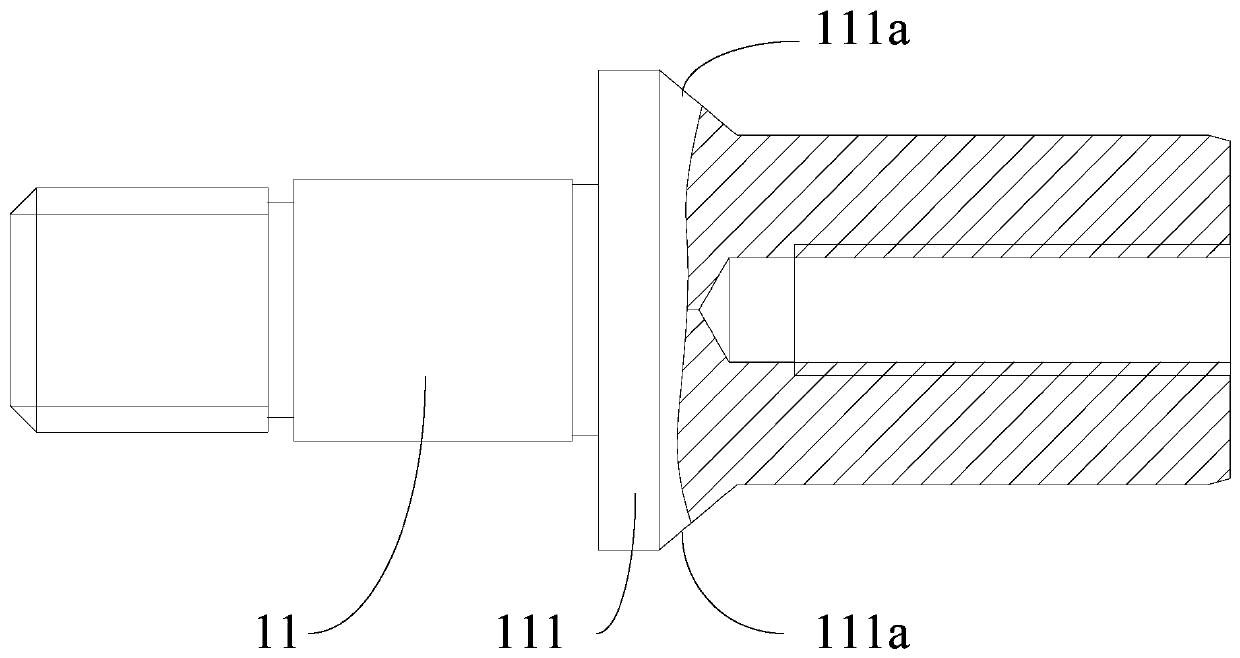
[0030] Wherein, the mounting part 1 includes a first pin shaft 11, a bushing 12 and a fixing part 13, one end of the first pin shaft 11 is installed on one end of the connecting arm 3, and the other end of the first pin shaft 11 is used to pass through the paddle A In the hoisting hole on the top, the middle part of the first pin shaft 11 is provided with a limit protrusion 111, and the limit protrusion 111 is against one side of the blade A, and one end of the bush 12 is sleeved on the other end of the first pin shaft 11 and Against the other side of the paddle A, the bushing 12 is arranged on the first pin shaft 11 through the fixing member 13 .

[0031] The hoisti...


PUM


Abstract

The invention discloses a hoisting tool for a paddle blade and belongs to the field of mechanical assembly. The hoisting tool comprises a mounting component, a hoisting component and a connecting arm.The mounting component comprises a first pin shaft, a lining and a fixing component. One end of the first pin shaft is mounted at one end of the connecting arm. The other end of the first pin shaft is used for penetrating a hoisting hole in the paddle blade. A limiting protrusion is arranged in the middle of the first pin shaft. The limiting protrusion abuts against one side of the paddle blade.The other end of the first pin shaft is sleeved with one end of the lining and the end of the lining abuts against the other side of the paddle blade. The lining is arranged on the first pin shaft through the fixing component. The hoisting component comprises a second pin shaft and a hoisting ring. One end of the second pin shaft is mounted at the other end of the connecting arm. A limiting plateis arranged at the other end of the second pin shaft. The outer rim of the limiting plate protrudes out of the outer peripheral wall of the second pin shaft. The hoisting ring is slidably arranged atthe other end of the second pin shaft. The hosting ring is located between the connecting arm and the limiting plate. By the adoption of the hoisting tool, steady and smooth hoisting of the paddle blade is achieved.

Description

technical field [0001] The invention belongs to the field of mechanical assembly, in particular to a hoisting tool for blades. Background technique [0002] The blade is one of the important components of the controllable pitch propeller. [0003] When processing and assembling the blades, the blades are usually bound by slings to realize the hoisting of the blades. However, due to the special-shaped structure of the blade, it is not easy to achieve a stable binding of the blade through the sling. If the operation is improper, it will cause the blade to tilt, unable to achieve balanced hoisting, and even cause the blade to fall, resulting in safety accidents and economic losses. . Contents of the invention [0004] In order to solve the problem that the blade is difficult to hoist, an embodiment of the present invention provides a hoisting tool for the blade. Described technical scheme is as follows: [0005] An embodiment of the present invention provides a hoisting t...

Claims


Application Information

Patent Timeline
Patent Type & Authority Patents(China)
IPC IPC(8): B66C1/24B66C1/12B66C1/36B66C13/06
Inventor 桑雪梅王帅赵章献
Owner WUHAN MARINE MACHINERY PLANT
Why Eureka
Try Eureka