
Power driven system and oil pumping unit applying same

A power-driven, pumping unit technology, applied in mechanical equipment, fluid pressure actuators, mining fluids, etc., can solve problems such as low mechanical efficiency of pumping units, easy fatigue damage of pumping units, and unsatisfactory energy-saving effects, etc. It achieves the effects of economical compactness and reasonableness, balanced lifting process, and convenient movement and adjustment

Inactive Publication Date: 2014-05-21
杨崇恩
View PDF7 Cites 0 Cited by
  • Summary
  • Abstract
  • Description
  • Claims
  • Application Information

AI Technical Summary

Problems solved by technology

[0003] The invention provides an energy-saving, high-efficiency, low-carbon and emission-reducing power drive system, and a pumping unit with simple structure, small volume, few mechanical vulnerable parts and long service life; The driving force required by the power system in the technology is large, the energy saving effect is not ideal, the pumping unit is prone to fatigue damage, and there are technical problems such as many failures
[0004] At the same time, the present invention also provides a power drive system with good sealing performance, high safety, automatic alarm, convenient and better sealing ring, and a foldable and easy-to-carry pumping unit; it solves the problems existing in the prior art The sealing structure of the power drive system is complicated, the mechanical efficiency of the pumping unit is low, and the technical problems of difficult handling

Method used


Image

  • Power driven system and oil pumping unit applying same
  • Power driven system and oil pumping unit applying same
  • Power driven system and oil pumping unit applying same

Examples


Embodiment

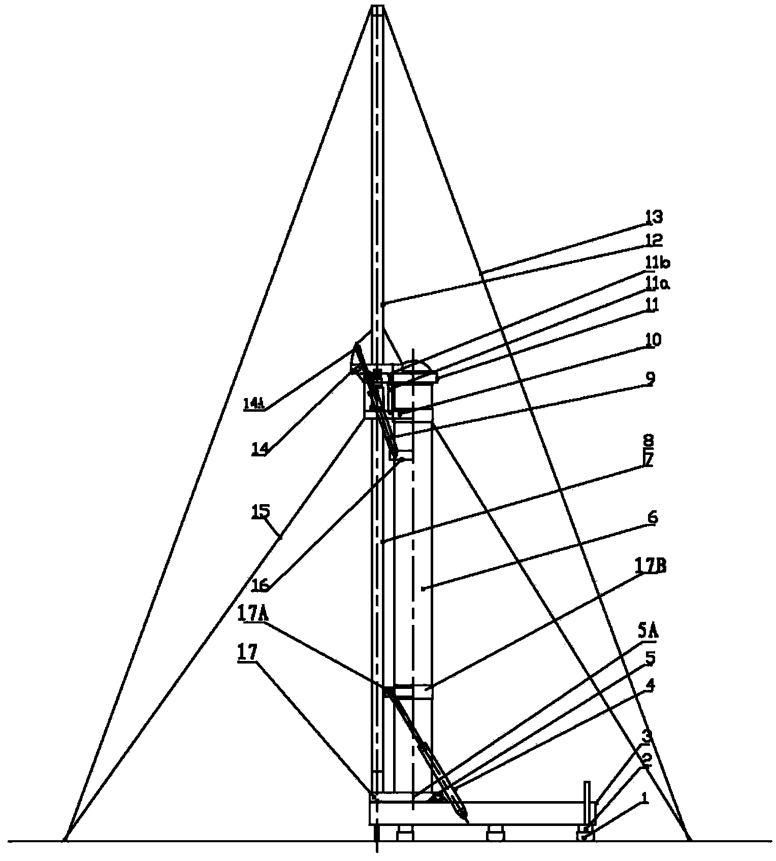
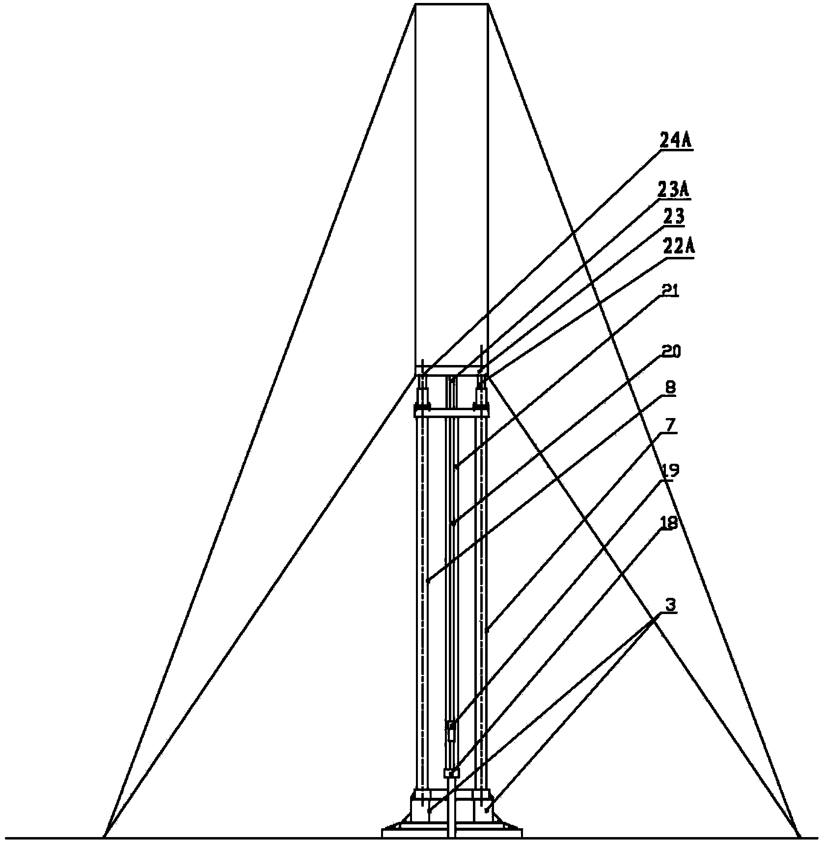
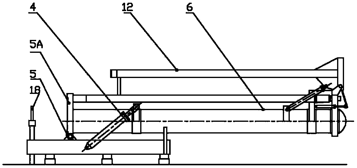
[0027] Such as figure 1 As shown, a pumping unit includes a fixed base 1, on which a horizontal slide rail 2 is fixed, and a movable adjustment seat 3 is installed on the horizontal slide rail 2, and the bottom of the movable adjustment seat 3 is provided with a horizontal slide The horizontal chute that rail 2 cooperates, movable base 5A is installed on movable adjustment seat 3, is provided with the longitudinal slide rail perpendicular to horizontal slide rail on the upper surface of movable adjustment seat 3, is provided with longitudinal sliding rail vertically on the bottom surface of movable base 5A. The projection that the slide rail cooperates, the relative position of the movable base 5A and the movable adjustment seat 3 are fixed by bolts 17 after being determined. The movable base 5A is fixed with the left plunger cylinder 7 at the front end, the right plunger cylinder 8 and the gas-liquid accumulator 6 positioned at the rear side of the plunger cylinder, the gas-l...


PUM


Abstract

The invention relates to a power transmission system and application thereof, in particular to a gas-liquid kinetic energy driven system and an oil pumping unit applying the same. The power driven system comprises a gas-liquid accumulator, an execution plunger cylinder, a plurality of reversing valves and a pressure pump, which form a driving oil way and an oil return way, and a closed loop consists of the driving oil way and the oil return way. The oil pumping unit adopts the driven system to drive an oil pumping rod to vertically move and can be folded. The power driven system saves energy resources and has high efficiency and good effects of low carbon and emission reduction, and the oil pumping unit has a simple structure, a small size, less easily-damaged mechanical parts and long service life. By the power driven system and the oil pumping unit, the technical problems that the power system in the prior art requires large motive power and has poor energy-saving effect, and the oil pumping unit is easily fatigue and damaged and has multiple faults are solved.

Description

technical field [0001] The invention relates to a power transmission system and its application, in particular to a gas-hydraulic kinetic energy drive system and a pumping unit using the system. Background technique [0002] At present, the oil extraction machinery adopted in the oil field all adopts the beam pumping unit and the beamless pumping unit with mechanical transmission. It consists of a rotating motor, decelerated by multi-stage gears, and converted into linear motion by the donkey head on the beam to drive the steel wire rope or chain to drive the oil pumping rod to move up and down to achieve the purpose of oil pumping. As Chinese patent " beam type hydraulic pumping unit (CN2561926Y) ", it is made up of two parts of machinery and hydraulic pressure. Among them, the mechanical part retains the original beam, donkey head, bracket, chassis, rope hanger and suspension rope; the hydraulic part includes four-chamber oil cylinder, main accumulator, reversing system, ...

Claims


Application Information

Patent Timeline
Patent Type & Authority Patents(China)
IPC IPC(8): F15B1/02F15B15/14E21B43/00
Inventor 杨崇恩
Owner 杨崇恩
Learn More