A double-layer sub-frame structure of an aerial work vehicle

A technology for aerial work vehicles and sub-frames, which is applied in the direction of lifting devices, etc., can solve the problems of beam fracture, difficulty in realizing the lightweight of the whole vehicle, and difficulty in the layout of the whole vehicle.

Active Publication Date: 2019-11-19
XUZHOU HANDLER SPECIAL VEHICLE
View PDF6 Cites 0 Cited by
  • Summary
  • Abstract
  • Description
  • Claims
  • Application Information

AI Technical Summary

Problems solved by technology

However, after the weight of the whole vehicle is reduced, the proportion of the weight of the chassis is greatly increased, and the influence of the position of the center of gravity of the chassis on the stability of high-altitude operations cannot be ignored, which makes it difficult to arrange the whole vehicle and realize the lightweight of the whole vehicle
[0004] like image 3 As shown, the sub-frame 1 of the existing aerial work vehicle is a single-layer rigid structure, and the sub-frame 1 is rigidly connected with the chassis body 3-1. -6 The entire vehicle body is propped up, and the tires are completely off the ground. At this time, the connection between the chassis cab 3-2 and the sub-frame forms a cantilevered state. Since the design of the chassis often does not consider such working conditions, such as If the girder is not reinforced at the joint, it is very easy to cause the girder to break

Method used


Image

  • A double-layer sub-frame structure of an aerial work vehicle
  • A double-layer sub-frame structure of an aerial work vehicle
  • A double-layer sub-frame structure of an aerial work vehicle

Examples


Embodiment Construction

[0013] In order to make the purpose, technical solutions and advantages of the embodiments of the present invention clearer, the technical solutions in the embodiments of the present invention will be clearly and completely described below in conjunction with the drawings in the embodiments of the present invention. Obviously, the described embodiments It is a part of embodiments of the present invention, but not all embodiments. Based on the embodiments of the present invention, all other embodiments obtained by persons of ordinary skill in the art without making creative efforts belong to the protection scope of the present invention.

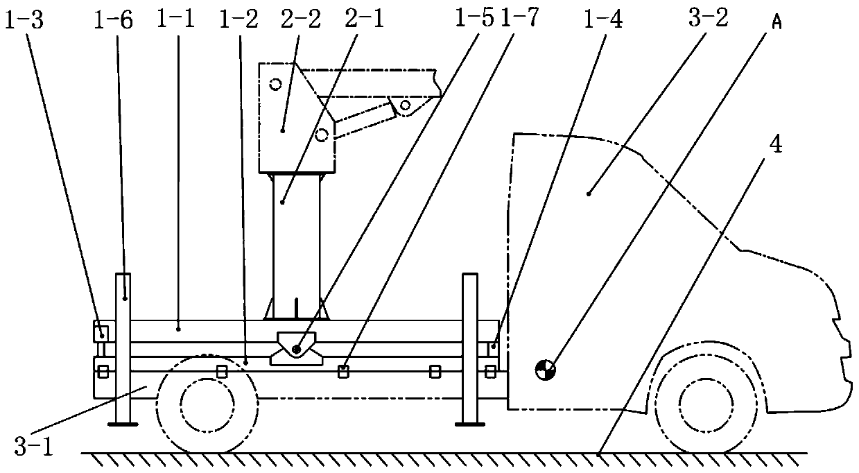
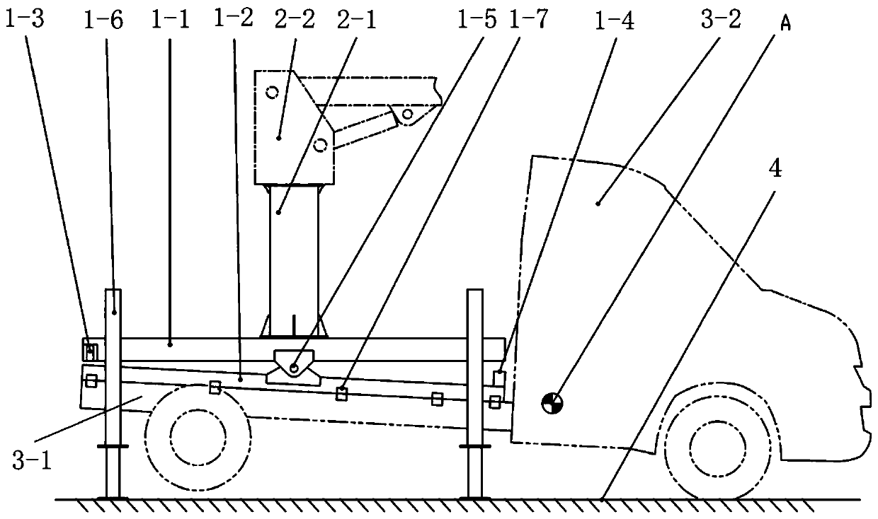
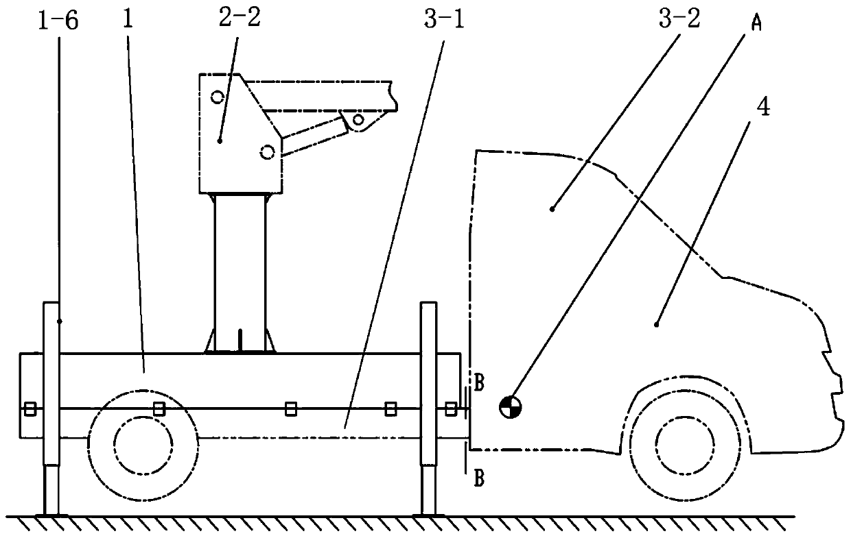
[0014] figure 1 and figure 2 A schematic structural view of a preferred embodiment of the present invention is shown, in which a double-layer sub-frame structure of an aerial work vehicle is composed of a lower frame 1-2, an upper frame 1-1, and a frame support 1 - Composed of 4 columns and the frame locking device 1-3, the upper frame 1-...


PUM


Abstract

A double-layer auxiliary frame structure of an aerial work vehicle, mainly composed of a lower frame, an upper frame, a frame support column and a frame locking device, the lower frame is installed on the chassis frame, and the upper The frame is hinged on the upper part of the lower frame, and the boom system for aerial work is installed above the upper frame. Outriggers are fixed around the upper frame, and the frame support columns and frame locking devices are set on the upper frame and the lower frame. Between the vehicle frames, and respectively positioned on the upper vehicle frame or the lower vehicle frame near one end of the chassis cab and one end close to the chassis rear. The invention can adjust the action point of the gravity of the chassis on the sub-frame, thereby better providing stability for high-altitude operations, improving the stability of the operation, and can also solve the problem that the tail girder of the cab needs to be specially strengthened to meet the operating conditions due to the suspension of the cab in the past. The problem.

Description

technical field [0001] The invention relates to a sub-frame structure of an aerial work vehicle, which is mainly used for connecting aerial work equipment with an automobile chassis frame, in particular to a sub-frame with a double-layer structure, which belongs to the field of special engineering work vehicles. Background technique [0002] With the continuous improvement of people's safety awareness, it has become a trend to use aerial work vehicles to replace traditional climbing ladders and scaffolding. Aerial work vehicles have many advantages such as high safety and high work efficiency. The current mainstream height of aerial work vehicles is 16 meters, the length of the whole vehicle is about 8 meters, and the weight of the whole vehicle is about 6 tons, which leads to many problems such as poor mobility, poor fuel economy, high cost of use, and high skill requirements for drivers. The demand for lightweight and miniaturization of aerial work vehicles is becoming st...

Claims


Application Information

Patent Timeline
Patent Type & Authority Patents(China)
IPC IPC(8): B66F11/04
CPCB66F11/04
Inventor 张泽华李培启李金柱王月云郑磊苑登波
Owner XUZHOU HANDLER SPECIAL VEHICLE
Why Eureka
Try Eureka