Mobile phone charge stand device

A mobile phone charging and charging stand technology, which is applied in the direction of circuit devices, battery circuit devices, collectors, etc., can solve the problems of inconvenience, cumbersome winding of charging lines, and the use of mobile phone charging, and achieve the effect of solving cumbersome winding

Pending Publication Date: 2018-01-19
昆山六二丰塑胶电子有限公司
0 Cites 0 Cited by

AI-Extracted Technical Summary

Problems solved by technology

[0005] Therefore, the object of the present invention is to provide a mobile phone charging stand device to s...

Method used

In summary, the mobile phone charging stand device of the present invention can firmly place the mobile phone 200 on the charging stand by the profiling groove 102 arranged in the charging stand body 101 and the retractable fixing blocks 107 at both ends of the groove superior. The charging can be carried out by inserting the interface of the mobile phone 200 into the plug 103 of the charging stand and connecting the USB interface 105 to connect to an external power supply. When there is no external power supply, the mobile phone 200 can be charged directly through the reserve ba...

Abstract

The invention discloses a mobile phone charge stand device which comprises a charge stand body, a profiled groove, a charge stand plug, a reserve battery device, USB (universal serial bus) interfacesand an indicator lamp. The profiled groove is formed in the charge stand body; the charge stand plug is arranged inside the profiled groove; the reserve battery device is arranged inside the charge stand body; the USB interfaces are arranged on the periphery of the charge stand body; the indicator lamp is arranged on the front surface of the charge stand body. The mobile phone charge stand devicehas the advantages that the problems of tedious charge wire winding, randomness in placing existing mobile phones and inconvenience in charging the existing mobile phones can be effectively solved bythe aid of the mobile phone charge stand device; a plurality of mobile phones can be synchronously charged by the aid of the mobile phone charge stand device, and information can be synchronously transmitted to the multiple mobile phones by the aid of the mobile phone charge stand device.

Application Domain

Batteries circuit arrangementsElectric power

Technology Topic

EngineeringReserve battery +4

Image

  • Mobile phone charge stand device
  • Mobile phone charge stand device
  • Mobile phone charge stand device

Examples

  • Experimental program(1)

Example Embodiment

[0028] The detailed features and advantages of the present invention are described in detail in the following embodiments. The content is sufficient to enable anyone familiar with the relevant art to understand the technical content of the present invention and implement it accordingly, and according to the content disclosed in this specification, the scope of patent application and drawings In this way, anyone who is familiar with the relevant art can easily understand the related purpose and advantages of the present invention. The following examples are to further illustrate the viewpoints of the present invention in detail, but do not limit the scope of the present invention with any implementation details.
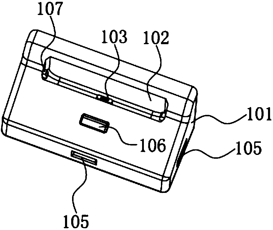
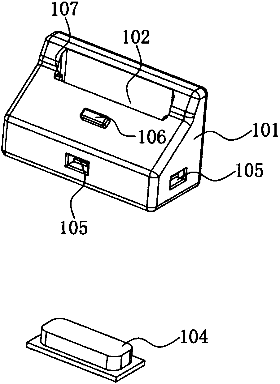
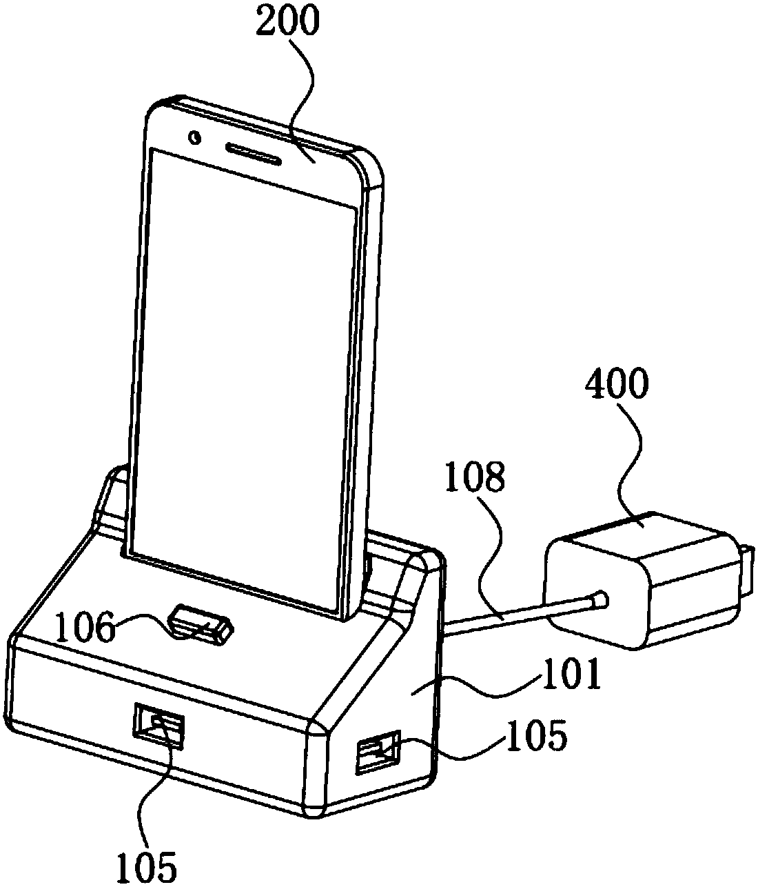
[0029] See figure 1 and figure 2 As shown, figure 1 It is a schematic diagram of the mobile phone charging stand device of the present invention. figure 2 It is an exploded schematic diagram of the mobile phone charging stand device of the present invention. The mobile phone charging stand device of the present invention includes:
[0030] Charging base body 101;
[0031] The profiling groove 102 is arranged on the charging base body 101;
[0032] The charging socket plug 103 is arranged at the inner position of the profiling groove 102;
[0033] The reserve battery device 104 is arranged inside the charging base body 101;
[0034] The USB ports 105 are respectively arranged around the charging base body 101;
[0035] The indicator light 106 is arranged on the front surface of the charging base body 101.
[0036] Wherein, telescopic fixing blocks 107 are provided at both ends of the profiling groove 102.
[0037] Wherein, the upper end of the telescopic fixed block 107 is provided with a chamfer.
[0038] Wherein, the storage battery device 104 is a rechargeable lithium battery.
[0039] Wherein, the charging base body 101 has at least two or more USB ports 105.
[0040] Wherein, the USB interface 105 is connected to the USB cable 108 to connect the mobile phone 200 for charging.
[0041] Wherein, the USB interface 105 is connected to a USB connection line 108 to connect an external power source to reserve power for the battery storage device 104.
[0042] Wherein, the USB interface 105 is connected to the USB cable 108 to connect the electronic device 300 to cooperate with the mobile phone 200 for information transmission.
[0043] The user puts the mobile phone 200 to be charged into the profiling groove 102 in the charging base body 101, and both ends of the groove are provided with retractable fixing blocks 107. In addition, both sides of the upper end of the retractable fixed block 107 are provided with chamfers to facilitate the insertion of the mobile phone 200. The mobile phone 200 can be firmly fixed in the profiling groove 102. At the center of the bottom end of the contoured groove 102, a charging dock plug 103 corresponding to the mobile phone 200 is provided, corresponding to the charging interface of the mobile phone 200. After the charging dock plug 103 is inserted into the charging port of the mobile phone 200, the charging dock can run corresponding functions.
[0044] A reserve battery device 104 is installed inside the charging base body 101, and the reserve battery device 104 is a rechargeable lithium battery. When the external power source is switched on, the reserve power source can be reserved for the reserve battery device 104. An indicator light 106 is also provided on the front surface of the charging base body 101, which lights up when the mobile phone 200 charging base is inserted into the charging base. The user is reminded that the mobile phone 200 has been connected to the charging dock, and the corresponding functional operations can be performed. A number of USB ports 105 are respectively provided around the charging base body 101, and the USB connection line 108 can be inserted according to the needs of the user to perform functional operations.
[0045] See image 3 As shown, image 3 It is a schematic diagram of the first embodiment of the mobile phone charging stand device of the present invention. In the first embodiment, the user inserts the mobile phone 200 into the charging dock, and inserts the charging dock plug 103 corresponding to the interface of the mobile phone 200, and the mobile phone 200 is firmly placed in the profiling groove 102 of the charging dock body 101. The indicator light 106 on the front surface of the charging base body 101 lights up. Remind users that they can start functional operations. With an external power supply, the user uses the USB cable 108, one end is inserted into the USB interface 105 of the charging base, and the other end is connected to the power plug 400. The user inserts the power plug 400 into an external power source to turn on the power. At this time, the charging stand starts to charge the mobile phone 200. While the charging operation is being performed, the storage battery device 104 located in the charging base body 101 starts to perform the power storage operation. When the power reserve of the reserve battery device 104 is full, the charging is automatically ended. When the charging of the mobile phone 200 is completed, only the mobile phone 200 needs to be pulled out of the charging base. When the user needs to charge multiple mobile phones 200, he only needs to plug the mobile phones 200 into the USB ports 105 around the charging base using the matching USB cable 108 to charge.
[0046] See Figure 4 As shown, Figure 4 It is a schematic diagram of the second embodiment of the mobile phone charging stand device of the present invention. In the second embodiment, when the user is limited by the environment of use and cannot provide external power, he only needs to insert the mobile phone 200 into the charging base, and plug the mobile phone 200 into the charging base plug 103 corresponding to the interface of the mobile phone 200. The mobile phone 200 is firmly placed in the charging base. In the profiling groove 102 of the main body 101. The indicator light 106 on the front surface of the charging base body 101 lights up. At this time, the reserve battery device 104 in the charging base body 101 starts to charge the mobile phone 200. When the user needs to charge multiple mobile phones 200, he only needs to plug the mobile phones 200 into the USB ports 105 around the charging base using the matching USB cable 108 to charge. When the charging of the mobile phone 200 is completed, only the mobile phone 200 needs to be pulled out of the charging base.
[0047] See Figure 5 As shown, Figure 5 It is a schematic diagram of the third embodiment of the mobile phone charging stand device of the present invention. In the third embodiment, when the user needs to transfer information inside the mobile phone 200, the user inserts the mobile phone 200 into the charging base, and inserts the charging base plug 103 corresponding to the interface of the mobile phone 200. The mobile phone 200 is firmly placed on the charging base body. In the profiling groove 102 of 101, the indicator light 106 on the front surface of the charging base body 101 lights up. The user inserts one end of the USB cable 108 into the USB interface 105 of any charging stand, and connects the other end to the electronic device 300 (such as a laptop or tablet). At this time, the information of the mobile phone 200 can be connected to the electronic device 300 through the charging stand. Match, so as to carry out information transmission. In the process of information transmission, the mobile phone 200 located in the charging dock can still be charged through an external power supply or a reserve power supply device. Both functional tasks are not affected by each other.
[0048] To sum up, the mobile phone charging base device of the present invention can firmly place the mobile phone 200 on the charging base through the profiling groove 102 provided in the charging base body 101 and the retractable fixing blocks 107 at both ends of the groove. Charging can be performed by plugging the mobile phone 200 interface into the charging dock plug 103 and connecting the USB interface 105 to the external power supply. When there is no external power supply, the mobile phone 200 can be charged directly through the reserve battery device 104 arranged inside the charging base, without connecting the USB cable 108. The USB connection line 108 can also be connected to the electronic device 300 through the USB interface 105 to cooperate with the mobile phone 200 for information transmission. Using the mobile phone charging stand device not only effectively solves the problems of cumbersome winding of the charging cable, random placement of the mobile phone 200 and inconvenient charging of the mobile phone 200, but also simultaneous charging and information transmission of multiple mobile phones.

PUM

no PUM

Description & Claims & Application Information

We can also present the details of the Description, Claims and Application information to help users get a comprehensive understanding of the technical details of the patent, such as background art, summary of invention, brief description of drawings, description of embodiments, and other original content. On the other hand, users can also determine the specific scope of protection of the technology through the list of claims; as well as understand the changes in the life cycle of the technology with the presentation of the patent timeline. Login to view more.
Why Eureka
Try Eureka