Vibration Actuators, Lens Drivers, and Ultrasonic Motors

An actuator and vibration technology, which is applied in the field of vibration actuators, lens drive devices and ultrasonic motors, can solve the problem of unstable driving characteristics of vibration actuators, and achieve the effect of stable driving characteristics

Active Publication Date: 2019-09-10
CANON KK
View PDF4 Cites 0 Cited by
  • Summary
  • Abstract
  • Description
  • Claims
  • Application Information

AI Technical Summary

Problems solved by technology

Therefore, the driving characteristic of the vibratory actuator is unstable

Method used


Image

  • Vibration Actuators, Lens Drivers, and Ultrasonic Motors
  • Vibration Actuators, Lens Drivers, and Ultrasonic Motors
  • Vibration Actuators, Lens Drivers, and Ultrasonic Motors

Examples


no. 1 approach

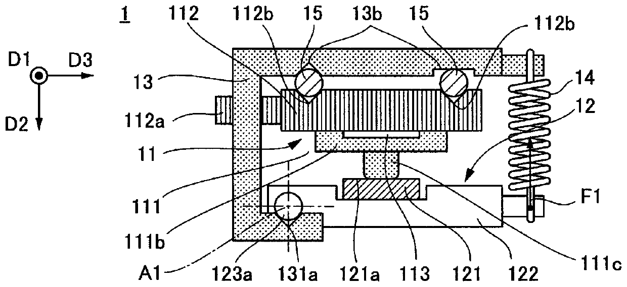
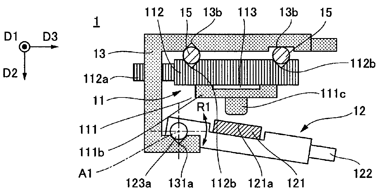
[0037] Figure 1A to Figure 1C It is a figure which shows the structure of a vibration actuator. Figure 1A to Figure 1C The illustrated vibration motor 1 is an ultrasonic motor used as a vibration actuator having a vibrator that ultrasonically vibrates by application of a high-frequency voltage. Of course, the scope of application of the present invention is not limited to ultrasonic motors. In addition, the present invention can be applied to a lens driving device including the vibration motor 1 .

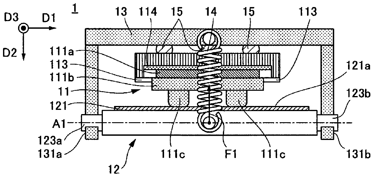
[0038] Figure 1A shows the driving direction from the vibrating motor 1 ( Figure 1A to Figure 1C The direction D1) is shown to observe the state. Figure 1B A state viewed from the side in the driving direction of the vibration motor 1 is shown. The vibration motor 1 includes a first member 11 , a second member 2 , a third member 13 and a pressurizing unit 14 .

[0039] The first member 11 includes a vibrator 111 vibrating by applying AC (alternating current) voltage, a vi...

no. 2 approach

[0064] Figure 3A to Figure 3C is a diagram showing the configuration of a vibration actuator according to a second embodiment. Figure 3A to Figure 3C The illustrated vibration motor 2 is an ultrasonic motor, which is a vibration actuator having a vibrator that vibrates ultrasonically by application of a high-frequency voltage. Of course, the scope of application of the present invention is not limited to ultrasonic motors. In addition, the present invention can be applied to a lens driving device including the vibration motor 2 .

[0065] Figure 3A shows the driving direction from the vibrating motor 2 ( Figure 3A to Figure 3C The direction D1) is shown to observe the state. Figure 3B A state viewed from the side in the driving direction of the vibration motor 2 is shown. Figure 3C showing along Figure 3B The state observed in the direction indicated by the arrow P shown. The vibration motor 2 includes a first member 21 , a second member 22 , a third member 23 an...


PUM


Abstract

A vibration type actuator includes a first member that has a vibrator; a second member that extends in a predetermined direction and has a friction sliding surface where the vibrator is press-contacted; a third member that rotatably holds the second member with respect to an axis parallel to the predetermined direction; and a pressing unit that generates a first force for rotating the second member with respect to the axis relative to the third member. The first member is sandwiched between the second member and the third member by the first force. The first member is driven in a driving direction parallel to the predetermined direction relative to the second member by the vibration of the vibrator.

Description

technical field [0001] The present invention relates to a vibration actuator, a lens driving device and an ultrasonic motor. Background technique [0002] A vibration-type actuator utilizing vibration of a piezoelectric element is small and generates a large driving force. Therefore, the vibratory actuator is compatible with a wide speed range and has low vibration and noise. There is known a vibration-type actuator that employs a method of simultaneously exciting a plurality of resonance modes on a chip-type vibrator provided with protrusions. The vibratory actuator induces elliptical motion of the protrusion of the vibrator, and relatively drives the friction member in pressure contact with the protrusion by frictional force. A vibratory actuator is characterized by a relatively small vibrator and a drive object that can be directly driven linearly. [0003] Patent Document 1 discloses a vibration motor for linearly driving a drive object using a chip-type vibrator. A ...

Claims


Application Information

Patent Timeline
Patent Type & Authority Patents(China)
IPC IPC(8): H02N2/04
CPCH02N2/0015H02N2/0055H02N2/026H02N2/04H02N2/0065
Inventor 大泽一治
Owner CANON KK
Why Eureka
Try Eureka