Control device, robot, and robot system

A control device and robot technology, applied in general control systems, control/regulation systems, program-controlled manipulators, etc., can solve problems such as differences, many operations, and long time, and achieve the effect of accurate operation

Inactive Publication Date: 2018-01-30
SEIKO EPSON CORP
View PDF1 Cites 14 Cited by
  • Summary
  • Abstract
  • Description
  • Claims
  • Application Information

AI Technical Summary

Problems solved by technology

In such conventional calibrations, generally speaking, the operator confirms the contact between the calibration jig and the correction manipulator, so there is a difference in the determination of the contact due to the operator.
For this reason, there is a problem that it is difficult to designate the position and posture of the calibration jig with high precision, and it takes a long time to designate the position and posture of the calibration jig if the operator wants to accurately judge the contact.
In addition, the operator directly performs a lot of work, and the more the number of robots, cameras, and reference surfaces to be calibrated increases, the more time is required to specify the position and posture of the calibration jig.

Method used


Image

  • Control device, robot, and robot system
  • Control device, robot, and robot system
  • Control device, robot, and robot system

Examples


Embodiment Construction

[0060] Hereinafter, the control device, robot, and robot system of the present invention will be described in detail based on preferred embodiments shown in the drawings.

[0061] robot system

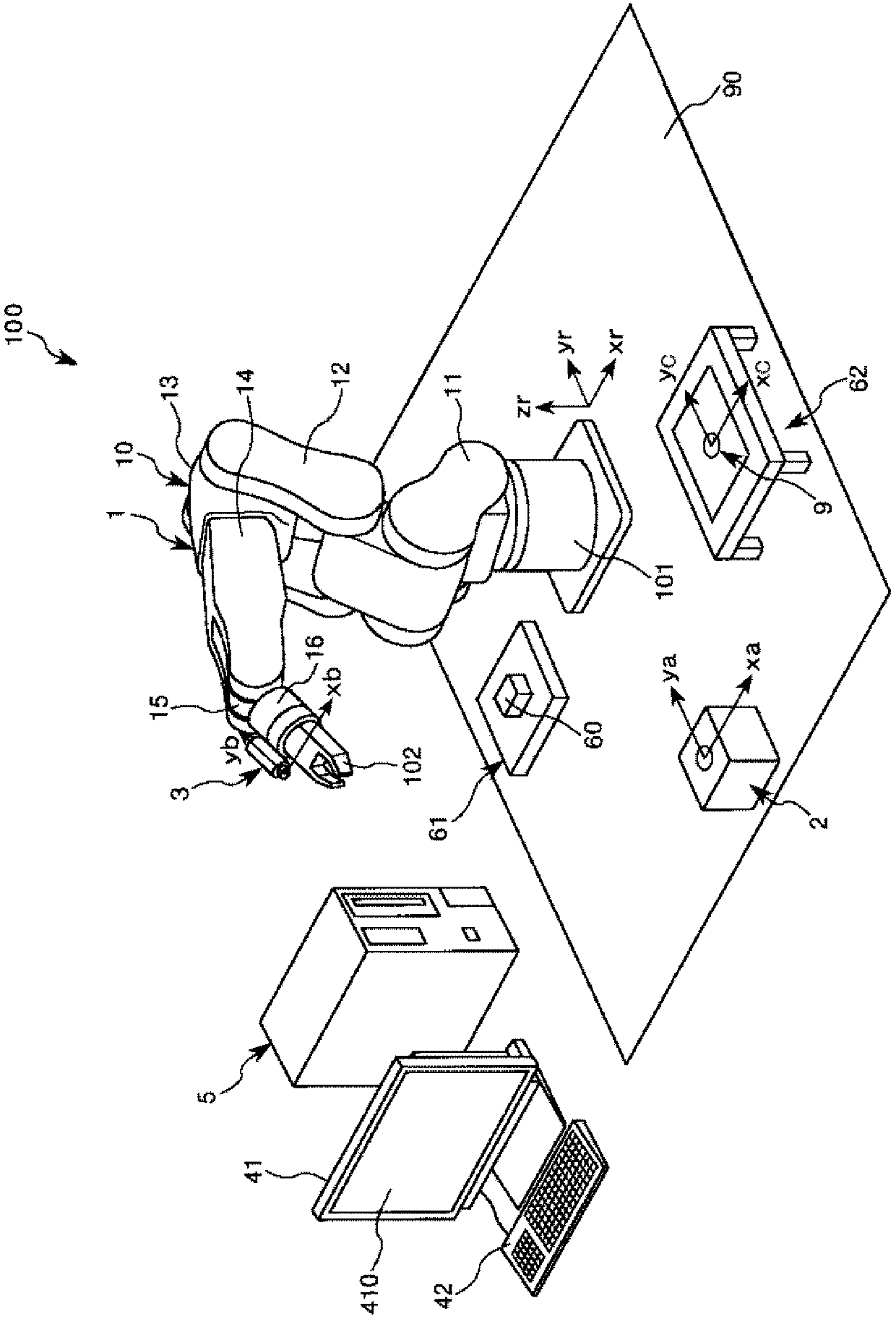
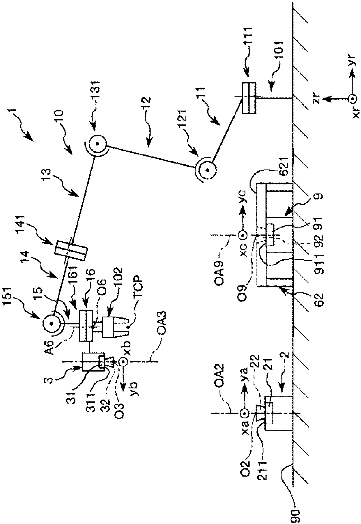
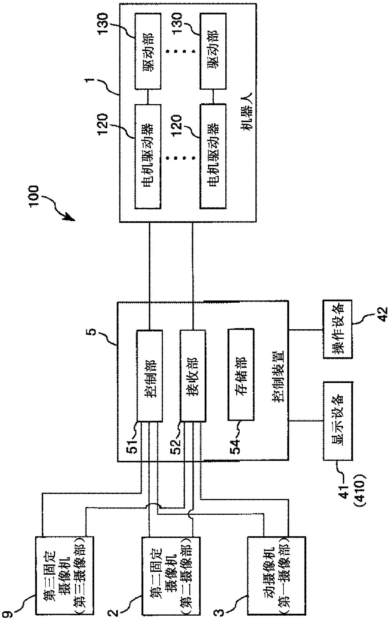
[0062] figure 1 It is a schematic perspective view showing the robot system according to the preferred embodiment of the present invention. figure 2 yes figure 1 A schematic diagram of the robot is shown. image 3 yes figure 1 A block diagram of the robotic system is shown. Figure 4 is expressed in image 3 Shown is a diagram of a window displayed in a screen that the display device has.

[0063] It should be noted that, in the following, for the convenience of explanation, the figure 2 The upper side is referred to as "upper" or "upper", and the lower side is referred to as "lower" or "below". Additionally, the figure 2 The up and down direction in the graph is defined as the "vertical direction", the surface intersecting the vertical direction is defined as the "horizont...


PUM


Abstract

The invention provides a control device, a robot and a robot system. The control device controls the robot with high working efficiency. The robot is controlled by the control device. The robot systemis equipped with the control device and the robot. The control device includes: a control portion and a receiving portion, in which the control portion is capable of allowing a robot to perform two or more works selected from first work of performing calibration between a coordinate system of a first imaging portion having an imaging function and a coordinate system of a robot, second work of performing calibration between a coordinate system of a second imaging portion having an imaging function and a coordinate system of the robot, third work of calculating a posture of a virtual standard surface that corresponds to a work surface on which the robot works, fourth work of calculating a distance between the first imaging portion and a standard point of the robot, and fifth work of calculating a distance between an end-effector and the standard point, based on one input command received by the receiving portion.

Description

technical field [0001] The invention relates to a control device, a robot and a robot system. Background technique [0002] For a long time, there have been known robot systems used for operations such as grasping, transporting, and assembling objects such as electronic components. Such a robot system includes: a robot including a robot arm having a plurality of arms and a robot hand provided at the tip of the robot arm; an imaging unit such as a camera; and a control device for controlling the robot and the imaging unit. The robot system with such a configuration causes the robot to perform various tasks on the target with the manipulator based on, for example, the image of the target captured by the imaging unit. [0003] Here, in order for the robot to accurately work on the target based on the image captured by the imaging unit, it is necessary to perform calibration (calibration) of the imaging unit to obtain the position on the image of the target captured by the imag...

Claims


Application Information

Patent Timeline
Patent Type & Authority Applications(China)
IPC IPC(8): B25J19/04B25J9/16G16Z99/00
CPCB25J9/1692B25J9/1697G16Z99/00B25J9/0096B25J9/02B25J9/1633B25J13/06G05B19/0426G05B19/414
Inventor 松浦健治宋钢
Owner SEIKO EPSON CORP
Why Eureka
Try Eureka