Measurement system and method for spatial analysis of dental implant restorations
A space analysis and measurement system technology, which is applied in the field of measurement system for dental implant restoration space analysis, can solve the problems of lack of accurate and efficient measurement methods and standards, difficult operation of ruler measurement, and poor measurement accuracy. , to achieve the effect of simple and accurate operation space, avoiding obstruction of surgical instruments, and direct occlusal distance inspection
- Summary
- Abstract
- Description
- Claims
- Application Information
AI Technical Summary
Problems solved by technology
Method used
Image
Examples
Embodiment 1
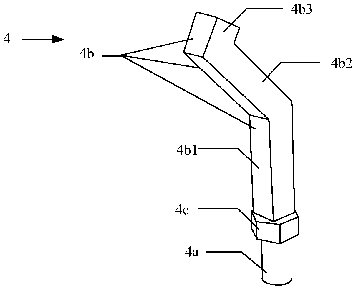
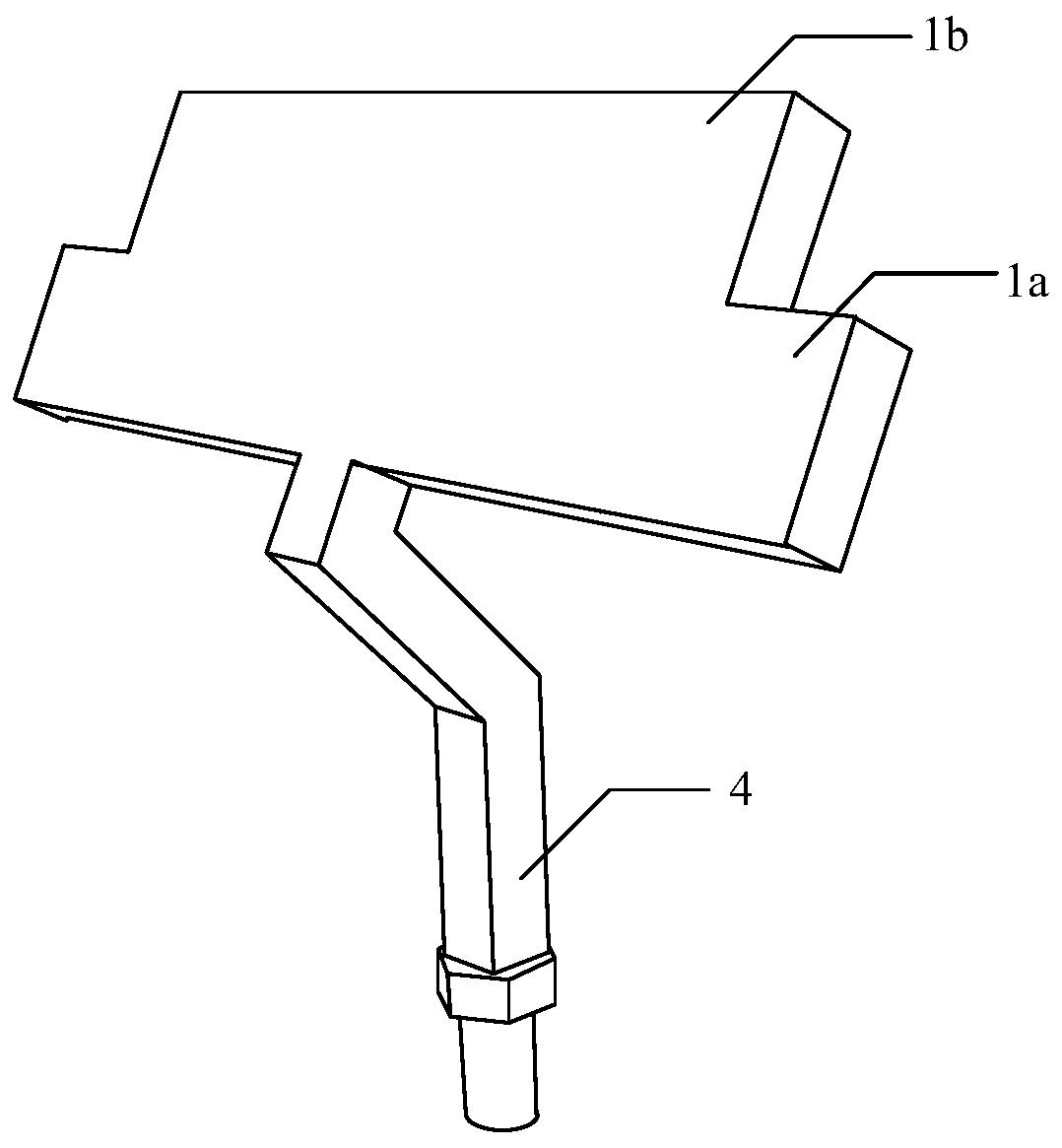
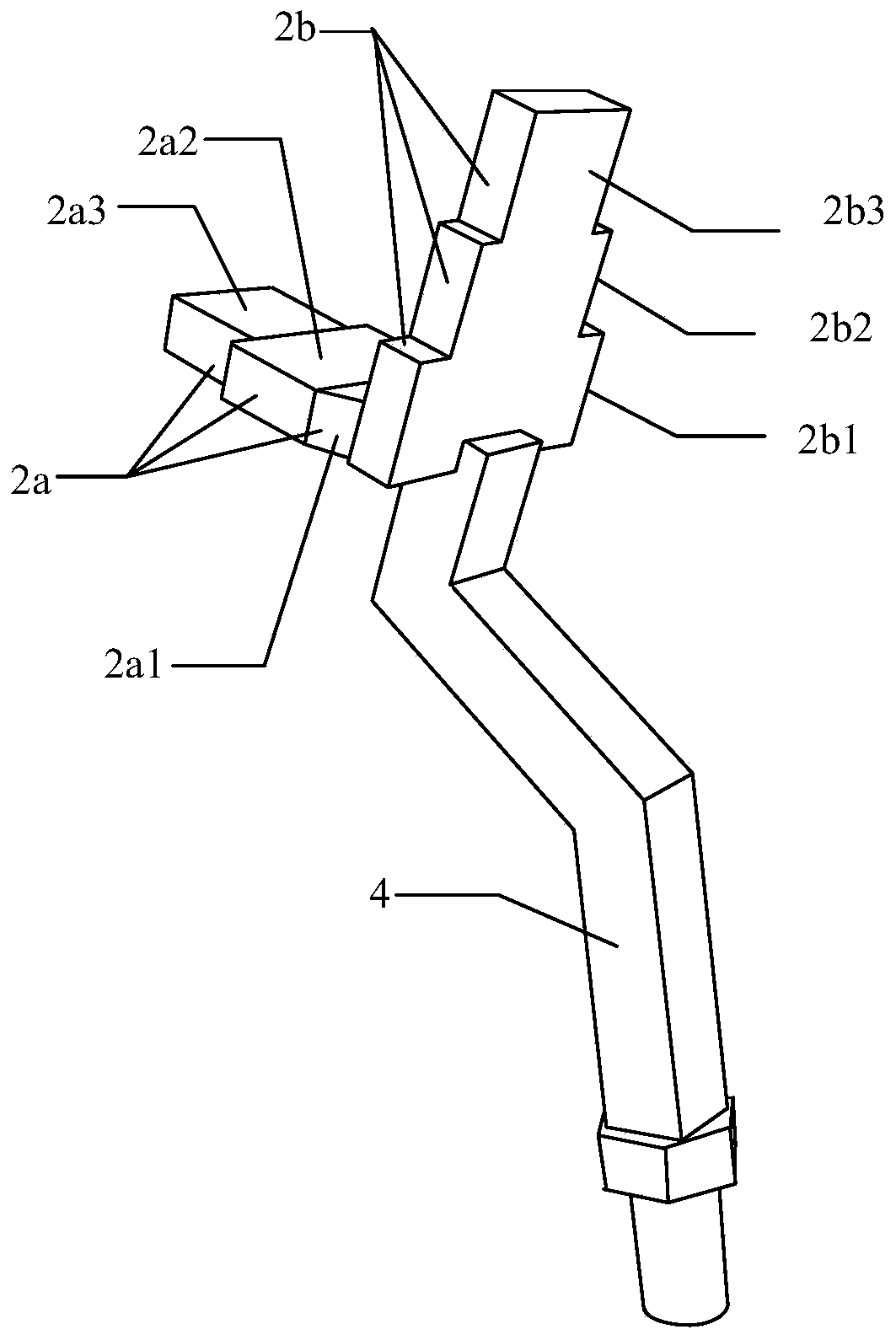
[0042] A measurement system for space analysis of oral implant restoration, including: the first measurement component for measuring the opening degree and the gap between multiple missing teeth, the second measuring component for measuring the gap between single missing teeth and the occlusal distance, and for measuring The third measuring component of the gingival penetration depth, the first measuring component, the second measuring component and the third measuring component all include an independent connecting rod and a measuring head arranged on the upper end of the connecting rod, that is, each measuring component has a A connecting rod and a measuring head, the measuring heads of the three measuring components are different, and the connecting rod can be the same. In this embodiment, the shapes of the connecting rods of the three measuring components are all the same.
[0043] Such as figure 1 As shown, the connecting rod 4 is a curved long rod, including a connectin...
Embodiment 2
[0054] On the basis of Embodiment 1, this embodiment also further improves the connecting rod 4:
[0055] When the middle connecting rod 4b2 is inclined toward the negative semi-axis direction of the z-axis, it is also inclined toward the negative half-axis direction of the x-axis, that is, backward, so that the middle connecting rod 4b2 and the lower connecting rod 4b1 are still in the xy plane An included angle C is formed on the top, and the angle of the included angle C is between 120°-180° and not equal to 180°, that is, the angle between the middle connecting rod 4b2 and the positive semi-axis of the y-axis is not greater than 60°, in other words the middle connecting rod 4b2 is also tilted backwards, within 60°.
[0056] The projections of the upper connecting rod 4b3 and the middle connecting rod 4b2 on the xy plane are as follows Figure 7 As shown, 5 is the projection of the middle connecting rod 4b2 on the xz plane, and 6 is the projection of the upper connecting r...
Embodiment 3
[0059] This embodiment is a further improvement of Embodiment 1, and provides specific dimensions for the measurement system of Embodiment 1 for the analysis of the dental implant restoration space.
[0060] (1) connecting rod
[0061] In this embodiment, the structures and sizes of the connecting rods of the first measuring component, the second measuring component and the third measuring component are completely the same. In other embodiments, the size of the connecting rods of one or more of the measuring components can be adjusted according to the needs of use.
[0062] In this embodiment, the connecting rod such as Figure 5 As shown, the lower end of the connecting rod 4 is a connecting cylinder 4a with a length of 5mm and a diameter of 3mm, and the connection between the connecting cylinder 4a and the connecting rod body 4b is a hexagon 4c with a height of 2mm and a side length of 2mm; The long rod has a cross-section of a square with a side length of 3mm. The connect...
PUM
 Abstract
Description
Claims
Application Information
 - R&D
- Intellectual Property
- Life Sciences
- Materials
- Tech Scout
- Unparalleled Data Quality
- Higher Quality Content
- 60% Fewer Hallucinations
Browse by: Latest US Patents, China's latest patents, Technical Efficacy Thesaurus, Application Domain, Technology Topic, Popular Technical Reports.
© 2025 PatSnap. All rights reserved.Legal|Privacy policy|Modern Slavery Act Transparency Statement|Sitemap|About US| Contact US: help@patsnap.com


