Substrate treating system

A technology for a substrate processing system and a substrate processing device, which is applied to conveyor objects, static electricity, electrical components, etc., and can solve problems such as the inability to remove static electricity from substrates

Active Publication Date: 2018-02-06
SEMES CO LTD
4 Cites 1 Cited by

AI-Extracted Technical Summary

Problems solved by technology

However, conventional ionizers are not actually effective in removing static electricity on substrate...

Method used

[0041] The fan filter unit 63 is a module integrating a filter and an air supply fan into one unit, and is a device for filtering fresh air and supplying the filtered air into the chamber. Clean air passes through the fan filter unit 63 and is supplied to the inside of the chamber 62 to form a vertical air flow. The vertical air flow of air provides a unifor...

Abstract

Disclosed is a substrate treating system. The substrate treating system includes an index unit having a port, on which a container containing a substrate is positioned, and an index robot, a process executing unit having substrate treating apparatuses for treating the substrate and a main transferring robot for transferring the substrate, and a buffer unit disposed between the process executing unit and the index unit and in which the substrate fed between the process executing unit and the index unit temporarily stays. Each of the index robot, the substrate treating apparatuses, the main transferring robot, and the buffer unit includes a conductive part contacting the substrate to remove static electricity of the substrate.

Application Domain

Semiconductor/solid-state device manufacturingConveyor parts +1

Technology Topic

EngineeringStatic electricity +1

Image

  • Substrate treating system
  • Substrate treating system
  • Substrate treating system

Examples

  • Experimental program(1)

Example Embodiment

[0022] The present invention can be variously modified and have various forms, and specific embodiments of the present invention will be shown in the accompanying drawings and described in detail. However, the present invention is not limited to a specific disclosure form, but it should be understood that the scope of the present invention includes all changes related to the spirit and technical scope of the present invention and their equivalents or substitutes. Detailed descriptions of known technologies related to the present invention will be omitted to avoid obscuring the technical essence of the present invention.
[0023] The terms used herein are only used to describe specific embodiments, and are not intended to limit the present invention. Singular terms may include plural forms unless otherwise specified. The terms "including" and "having" are used to indicate that the features, numbers, steps, operations, elements, components or their combinations described in the specification exist, and can be understood as adding one or more other features, numbers, and steps , Operation, element, component or their combination.
[0024] Terms such as "first" and "second" can be used to describe various elements, but these elements are not limited to these terms. These terms can only be used to distinguish one element from another.
[0025] Hereinafter, embodiments of the present invention will be described with reference to the drawings, and in the description of the present invention, regardless of the reference numerals, the same reference numerals are given to the same or similar elements, and their repeated description will be omitted.
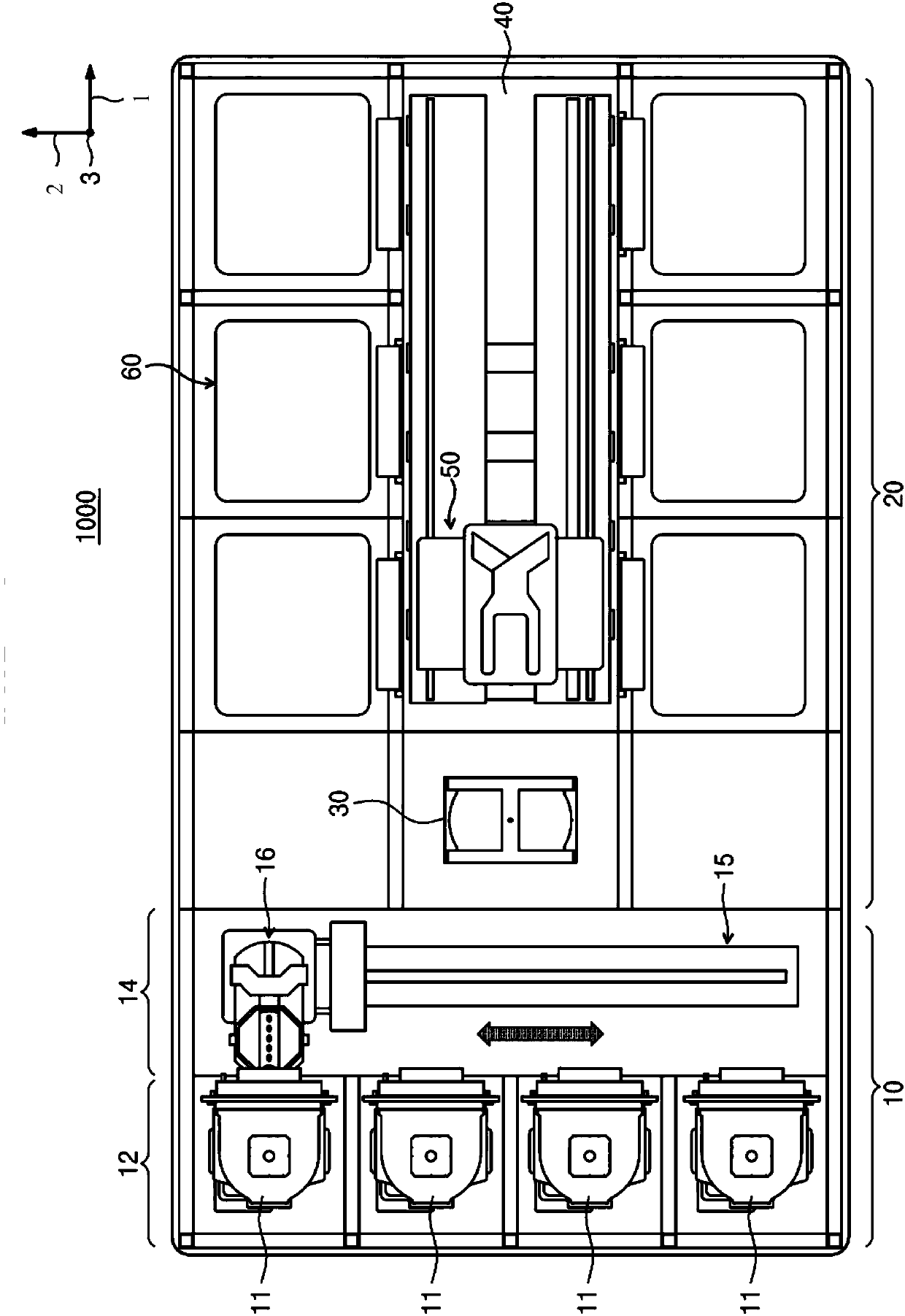
[0026] figure 1 It is a top view schematically showing the substrate processing system according to the present invention.
[0027] See figure 1 , The substrate processing system 1000 according to the present invention may include an index unit 10 and a process execution unit 20. The index unit 10 and the process execution unit 20 are arranged in a row. Hereinafter, the direction in which the index unit 10 and the process execution unit 20 are arranged is referred to as the first direction 1, and the direction perpendicular to the first direction 1 when viewed from the top is referred to as the second direction 2, and will be combined with the first direction. The direction perpendicular to the plane of 1 and the second direction 2 is called the third direction 3.
[0028] The index unit 10 is arranged at the front of the substrate processing system 1000 along the first direction 1. The index unit 10 includes a transmission frame 14 and a plurality of load ports 12.
[0029] The carrier 11 accommodating the substrate W is located at the load port 12. A plurality of load ports 12 are provided and the plurality of load ports 12 are arranged in a row along the second direction 2. However, the number of load ports 12 may be increased or decreased according to the process efficiency or floor space of the substrate processing system 1000. A front opening wafer box (FOUP) can be used as the carrier 11. The carrier 11 has a plurality of slots for accommodating the substrate, and the substrate is arranged parallel to the ground.
[0030] The transfer frame 14 is arranged to be adjacent to the load port 12 in the first direction. The transfer frame 14 is arranged between the load port 12 and the buffer unit 30 of the process execution unit 20. The transport frame 14 includes an index rail 15 and an index robot 16. The index robot 16 is located on the index rail 15. The index robot 16 transfers the substrate W between the buffer unit 30 and the carrier 11. The index manipulator 16 moves linearly along the index guide 15 in the second direction 2 or rotates around the third direction 3.
[0031] The process execution unit 20 is arranged at the rear of the substrate processing system 1000 along the first direction 1 and is adjacent to the index unit 10. The process execution unit 20 includes a buffer unit 30, a moving path 40, a main transfer robot 50 and a substrate processing device 60.
[0032] The buffer unit 30 is arranged in front of the process execution unit 20 along the first direction 1. The buffer unit 30 is a space where the substrate W is temporarily received and before being transferred between the substrate processing apparatus 60 and the carrier 11. A slot is provided in the buffer unit 30 (see Figure 4 ), the substrate W is placed in the slot, and a plurality of slots are spaced apart from each other along the third direction 3.
[0033] The moving path 40 is arranged to correspond to the buffer unit 30. The length direction of the moving path 40 is parallel to the first direction. The moving path 40 provides a passage through which the main conveying robot 50 moves. The substrate processing devices 60 are arranged to face each other on opposite sides of the movement path 40 along the first direction 1. The main transfer robot 50 moves along the first direction 1 through the moving path 40, and is equipped with a moving guide rail, along which the main transfer robot 50 can be raised and lowered to the upper and lower parts of the substrate processing apparatus 60 and the upper and lower parts of the buffer unit 30 .
[0034] The main transfer robot 50 is installed in the movement path 40 and transfers the substrate W between the substrate processing apparatus 60 and the buffer unit 30 or between the plurality of substrate processing apparatuses 60. The main transport robot 50 linearly moves along the movement path 40 in the first direction 1 or rotates around the third direction 3.
[0035] The substrate processing apparatus 60 is provided in plural, and is arranged on opposite sides of the moving path 40 along the first direction 1. Some substrate processing devices 60 are arranged along the length direction of the moving path 40. In addition, some substrate processing apparatuses 60 are arranged stacked on top of each other. That is, the substrate processing apparatus 60 having an A by B array may be arranged on one side of the moving path 40. Here, A is the number of substrate processing apparatuses 60 arranged in a row along the first direction 1, and B is the number of substrate processing apparatuses 60 arranged in a row along the third direction 3. When four or six substrate processing apparatuses 60 are provided on one side of the movement path 40, the substrate processing apparatuses 60 may be arranged in a 2×2 or 3×2 array. The number of substrate processing devices 60 can be increased or decreased. The difference is that the substrate processing device 60 may only be provided on one side of the moving path 40. In addition, different from the foregoing, the substrate processing device 60 may be provided on one side or opposite sides of the moving path 40 in a single layer.
[0036] The substrate processing device 60 may perform a cleaning process on the substrate W. The substrate processing apparatus 60 may have different structures according to the type of cleaning process. Alternatively, the substrate processing apparatuses 60 may have the same structure. Optionally, the substrate processing apparatus 60 is divided into a plurality of groups, so that the substrate processing apparatuses 60 belonging to the same group have the same structure, and the substrate processing apparatuses 60 belonging to different groups have different structures. For example, when the substrate processing apparatus 60 is divided into two groups, the substrate processing apparatus 60 belonging to the first group may be arranged on one side of the moving path 40, and the substrate processing apparatus 60 belonging to the second group may be arranged on the opposite side of the moving path 40. side. Optionally, the substrate processing apparatus 60 belonging to the first group and the substrate processing apparatus 60 belonging to the second group may be respectively disposed on the upper layer and the lower layer on the opposite side of the moving path 40. The first group of substrate processing apparatuses 60 and the second group of substrate processing apparatuses 60 may be classified according to the type of chemical used or the type of cleaning method. The difference is that the first group of substrate processing apparatuses 60 and the second group of substrate processing apparatuses 60 can sequentially perform processes on one substrate W.
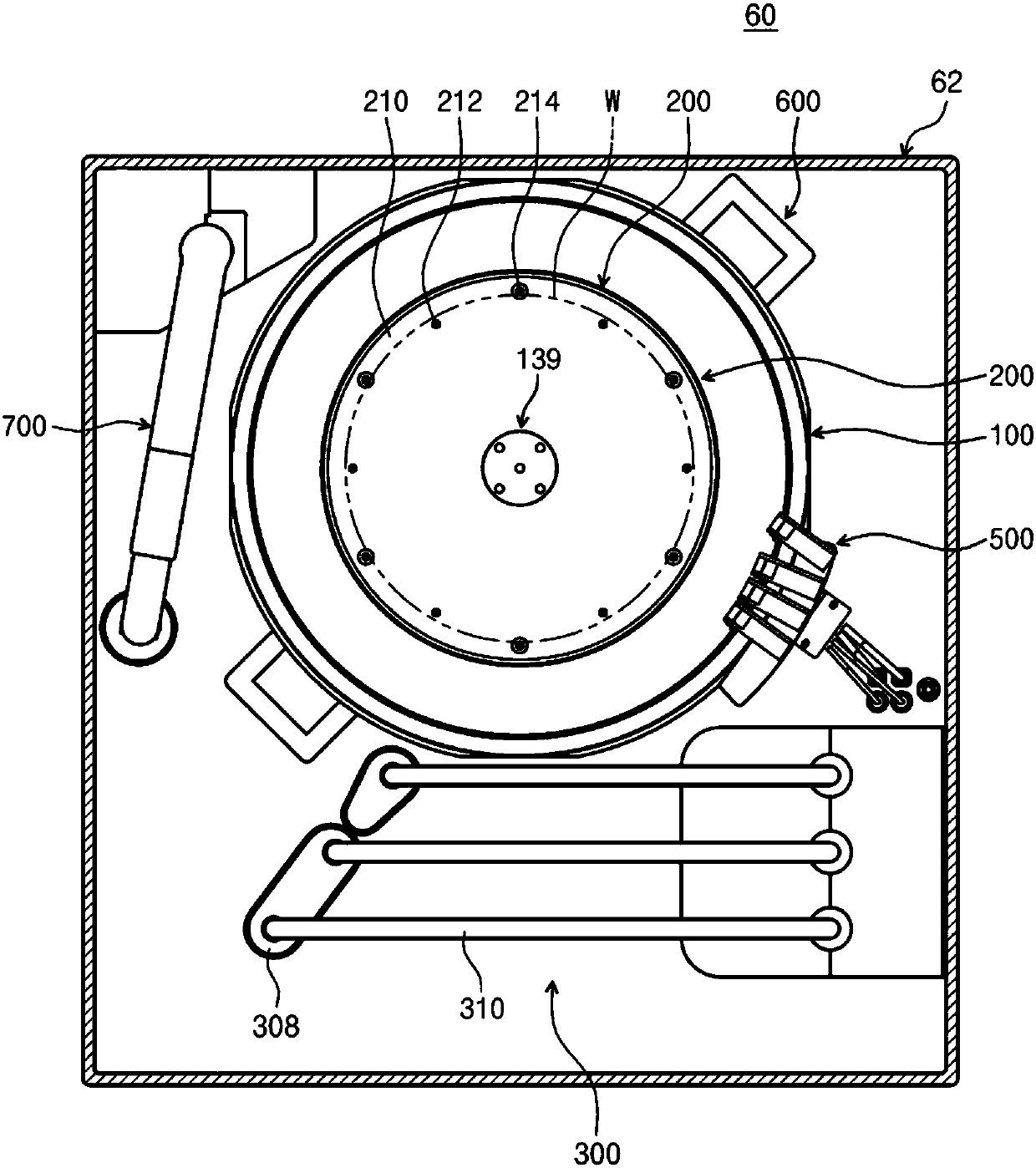
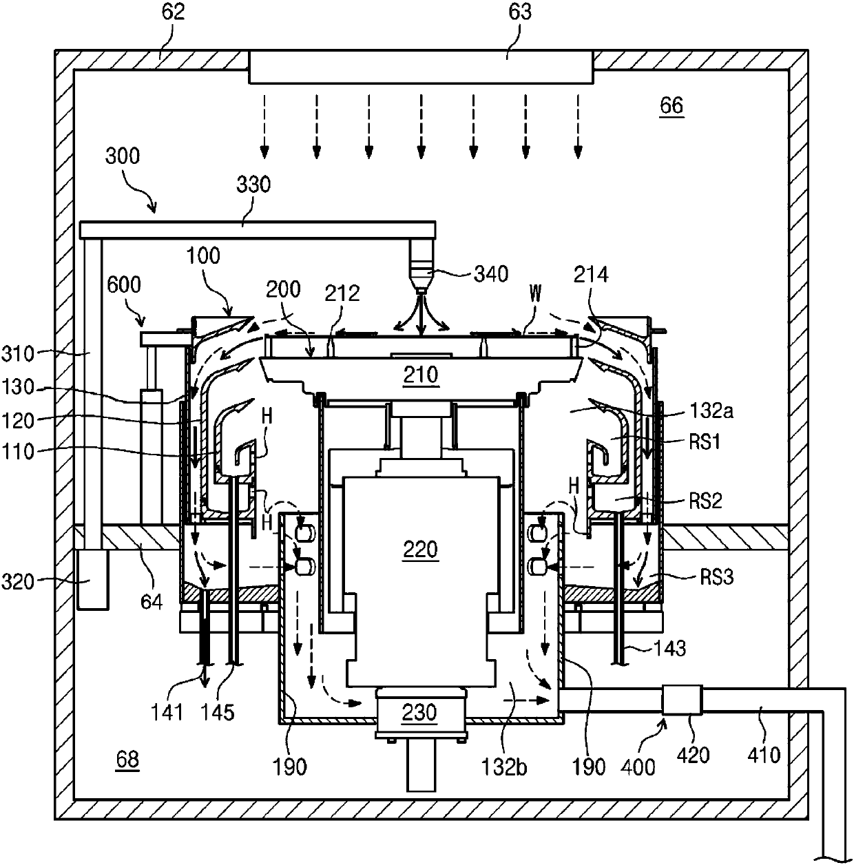
[0037] figure 2 It is a plan view showing the structure of a single wafer type substrate processing apparatus according to the present invention. image 3 Is shown figure 2 A cross-sectional view of the processing container and the substrate supporting member in the substrate processing apparatus of.
[0038] Although it has been described as an example that the substrate processed by the single wafer type substrate processing apparatus 1 is a semiconductor substrate, the present invention is not limited to this, but can be applied to various substrates such as a liquid crystal display device or a glass substrate .
[0039] See figure 2 with image 3 , The substrate processing apparatus 60 according to the present invention is an apparatus for removing foreign matter and excess film on the surface of a substrate by using various processing liquids, and the apparatus includes a chamber 62, a processing container 100, a substrate support member 200, and a first swing nozzle unit 300 , The fixed nozzle 500, the second swing nozzle unit 700 and the exhaust member 400.
[0040] The chamber 62 provides a closed internal space, and a fan filter unit 63 is installed on the top of the chamber 62. The fan filter unit 63 generates a vertical airflow inside the chamber 62.
[0041] The fan filter unit 63 is a module that integrates a filter and an air supply fan into one unit, and is a device for filtering fresh air and supplying the filtered air into the chamber. The clean air passes through the fan filter unit 63 and is supplied to the inside of the chamber 62 to form a vertical airflow. The vertical airflow of air provides a uniform airflow to the substrate, and the pollutants (exhaust gas) generated during the processing of the substrate surface by the processing liquid are discharged to the exhaust member through the suction pipe of the processing container 100 together with the air. 400 is thereby removed, so that the interior of the processing container maintains a high degree of cleanliness.
[0042] The chamber 62 is divided into a process area 66 and a maintenance area 68 by a horizontal partition 64. The maintenance area 68 is a space in which in addition to the discharge lines 141, 143, and 145 and the sub-exhaust line 410 connected to the processing container 100, a driver for the lifting unit and a driver 300b for the first swing nozzle unit 300 are also provided. And supply lines, although only some of them are shown in the drawings. Preferably, the maintenance area 68 is separated from the process area in which the substrate is processed.
[0043] The processing container 100 has an open cylindrical shape, and provides a process space for processing the substrate W. The upper surface of the opening of the processing container 100 is set as a passage through which the substrate W is loaded/unloaded. The substrate support member 200 is located inside the processing container 100. During the process, the substrate support member 200 supports the substrate W and rotates the substrate W.
[0044] See image 3 The processing container 100 provides an upper space 132a where the rotating head 210 is located and a lower space 132b distinguished from the upper space 132a by the rotating head 210, wherein an exhaust pipe 190 is connected to the lower end of the lower space 132b so that exhaust can be forced. The first annular suction pipe 110, the second annular suction pipe 120, and the third annular suction pipe 130 for guiding and sucking the processing liquid, gas and exhaust gas sputtered on the rotating substrate in a multi-stage arrangement are arranged in the processing container 100 in the upper space 132a. Each of the first annular suction pipe 110, the second annular suction pipe 120, and the third annular suction pipe 130 has an exhaust hole H communicating with a common annular space (corresponding to the lower space of the container). An exhaust pipe 190 connected to the exhaust member 400 is provided in the lower space 132b.
[0045] Specifically, each of the first to third suction pipes 110, 120, and 130 includes a bottom surface having a ring shape and a side wall extending from the bottom surface and having a cylindrical shape. The second suction pipe 120 surrounds the first suction pipe 110 and is spaced apart from the first suction pipe 110. The third suction pipe 130 surrounds the second suction pipe 120 and is spaced apart from the second suction pipe 120.
[0046] The first to third suction pipes 110, 120, and 130 provide first to third recovery spaces RS1, RS2, and RS3, and the processing liquid sputtered from the substrate W and gas containing exhaust gas are introduced into the recovery spaces RS1, RS2, and RS3 . The first recovery space RS1 is defined by the first suction pipe 110, the second recovery space RS2 is defined by the space between the first suction pipe 110 and the second suction pipe 120, and the third recovery space RS3 is defined by the second suction pipe 120 and the third suction pipe 120. The space between the suction pipes 130 is defined.
[0047] The centers of the upper surfaces of the first to third suction pipes 110, 120, and 130 are open and have an inclined surface whose distance from the bottom surface gradually increases from the side wall to the opening. Therefore, the treatment liquid sputtered from the substrate W flows into the recovery spaces RS1, RS2, and RS3 along the upper surfaces of the first to third suction pipes 110, 120, and 130.
[0048] The first treatment liquid introduced into the first recovery space RS1 is discharged to the outside through the first recovery line 145. The second treatment liquid introduced into the second recovery space RS2 is discharged to the outside through the second recovery line 143. The third treatment liquid introduced into the third recovery space RS3 is discharged to the outside through the third recovery line 141.
[0049] At the same time, the processing container 100 is coupled to the lifting unit 600, and the lifting unit 600 changes the vertical position of the processing container 100. The lifting unit 600 linearly moves the container 100 upward and downward. When the container 100 moves up and down, the relative height of the container 100 and the rotating head 210 changes. The processing container 100 is lowered so that when the substrate W is loaded on or unloaded from the rotary head 210, the rotary head 210 protrudes to the upper side of the processing container 100.
[0050] When the process is performed, the height of the container 100 is adjusted so that the processing liquid is introduced into the suction pipes 110, 120, and 130 according to the kind of processing liquid supplied to the substrate W. Therefore, the relative vertical position between the processing container 100 and the substrate W is changed. Therefore, the processing container 100 can make different types of processing liquid and polluted gas recovered in the recovery spaces RS1, RS2, and RS3.
[0051] In this embodiment, the substrate processing apparatus 60 vertically moves the processing container 100 to change the relative vertical position between the processing container 100 and the substrate supporting member 200. However, the substrate processing apparatus 60 may vertically move the substrate supporting member 200 to change the relative vertical position between the processing container 100 and the substrate supporting member 200.
[0052] The substrate support member 200 is installed inside the processing container 100. The substrate support member 200 may support the substrate W during the process, and may be driven to rotate during the process by the driver 230, which will be described below. The substrate supporting member 200 has a spin head 210 having a circular upper surface, a support pin 212 supporting the substrate W, and a chuck pin 214 provided on the upper surface of the spin head 210. The supporting pins 212 are arranged in a specific array at a distance from each other on the periphery of the upper surface of the rotating head 210 and protrude upward from the rotating head 210. The support pin 212 supports the lower surface of the substrate W so that when the substrate W leaves the spin head 210 upward, the substrate W is supported. The chuck pin 214 is arranged on the outer side of the support pin 212 and protrudes upward. The chuck pin 214 arranges the substrate W so that the substrate W supported by the plurality of support pins 212 can be positioned at an appropriate position on the spin head 210. During the process, the chuck pin 214 contacts the side of the substrate W to prevent the substrate W from deviating from the correct position.
[0053] The support shaft 220 supporting the rotating head 210 is connected to the lower side of the rotating head 210, and the support shaft 220 is rotated by a driver 230 connected to the lower end of the support shaft 220. The driver 230 may be a motor or the like. When the support shaft 220 rotates, the spin head 210 and the substrate W are rotated.
[0054] The exhaust member 400 provides exhaust pressure (suction pressure) to the first to third suction pipes 110, 120, and 130 during the process. The exhaust member 400 includes a damper 420 and a sub exhaust line 410 connected to the exhaust pipe 190. The sub-exhaust line 410 receives exhaust pressure from an exhaust pump (not shown), and the sub-exhaust line 410 is connected to a main exhaust line buried in the bottom space of a semiconductor production line (manufacturing facility).
[0055] The fixed nozzle unit 500 is fixedly installed at the upper end of the processing container 100 and supplies ultrapure water, ozone water, and nitrogen to the center of the substrate.
[0056] In this embodiment, the first swing nozzle unit and the second swing nozzle unit may be processing liquid spraying units.
[0057] The second swing nozzle unit 700 swings to the upper side of the center of the substrate to supply fluid for drying the substrate onto the substrate. The fluid used for drying may include isopropanol and high temperature nitrogen.
[0058] The first swing nozzle unit 300 is located outside the processing container 100. The first swing nozzle unit 300 rotates by cantilever swing, and supplies processing liquids (acidic liquid, alkaline liquid, neutral liquid, and dry gas) for cleaning or etching the substrate to the substrate W located on the spin head 210. Such as figure 2 As shown, it can be seen that since the plurality of first swing nozzle units 300 are arranged in parallel and the distance between each first swing nozzle unit 300 and the processing container 100 is different, the length of each first swing nozzle unit 300 is different according to its rotation radius .
[0059] Each of the first swing nozzle unit 300 may include a support shaft 310, a driver 320, a nozzle support 330, and a nozzle 340. The length direction of the support shaft 310 is the third direction, and the lower end of the support shaft 310 is connected to the driver 320. The driver 320 rotates and raises the support shaft 310. The nozzle support 330 is vertically connected to the end of the support shaft 310 opposite to the end connected to the driver 320. The nozzle 340 is installed on the bottom surface of the end of the nozzle support 330. The nozzle 340 is moved to the process position and the standby position by the driver 320. The process position is a position where the nozzle 340 is arranged vertically above the center of the substrate, and is a position where the nozzle 340 is separated from the upper side of the substrate.
[0060] Meanwhile, in the substrate processing system 1000, the substrate W is in contact with the index robot 16, the buffer unit 30, the main transport robot 50, and the rotary head 210 of the substrate processing apparatus, and each unit (index robot, substrate processing apparatus, The main transfer robot and the buffer unit) include conductive parts for removing static electricity from the substrate.
[0061] See Figure 4 , The rotating head 210 may include a first conductive part 213. The first conductive part 213 may be provided in the support pin 212 and contact the substrate, or the entire support pin 212 may be formed of a conductive material.
[0062] The main transfer robot 50 may have a first blade 52 on which a substrate is placed, and the first blade 52 may include a second conductive part 54 in contact with the substrate.
[0063] The buffer unit 30 may have a slot 32 in which the substrate is placed, and the slot may include a third conductive part 34 that contacts the bottom surface of the substrate.
[0064] The index robot 16 may have a second blade 17 on which a substrate is placed, and the second blade 17 may include a fourth conductive part 18 in contact with the substrate.
[0065] The first conductive portion 213, the second conductive portion 54, the third conductive portion 34, and the fourth conductive portion 18 may be formed of conductive materials having different surface resistances. That is to say, the first conductive portion 213, the second conductive portion 54, the third conductive portion 34, and the fourth conductive portion 18 may have such a surface resistance that the static electricity removing ability can be adjusted according to the substrate processing apparatus 60, the main transfer robot 50, The order of the buffer unit 30 and the index robot 16 increases in order. At the same time, the conductive part is connected to the ground wire to discharge the static electricity of the substrate to the outside.
[0066] As an example, the first conductive part 213 may include a conductive material (carbon (30%) polyether ether ketone) having a surface resistance of 10^6Ω/sq, and the second conductive part 54 may include a conductive material having a surface resistance of 10^5Ω/sq. Material (carbon (50%) polyether ether ketone), the third conductive part 34 may include a conductive material (nanocarbon polyether ether ketone) having a surface resistance of 10^4Ω/sq, and the fourth conductive part 18 may include Conductive material (aluminum) with 3Ω/sq surface resistance.
[0067] Meanwhile, each of the conductive parts 213, 54, 34, and 18 may include a heat dissipation plate structure to increase the static electricity removal capability, and the number of contact points may be increased from four to six.
[0068] In this way, static electricity is removed in stages from the spin head 210 through sequential increase of conductivity. When the residual static electricity of the substrate with a critical size of 90μm drops below 100V/cm, and the residual static electricity of the substrate with a critical size of 14μm When it drops below 15V/cm, the pattern damage caused by the instantaneous charge difference can be reduced. According to the embodiment of the present invention, pattern damage caused by the instantaneous charge difference can be avoided by removing static electricity from the substrate in stages.
[0069] According to the embodiments of the present invention, the effect of removing static electricity from the substrate can be enhanced.
[0070] The effects of the present invention are not limited to the above-mentioned effects, and those skilled in the art to which the present invention pertains can clearly understand the unmentioned effects from the description and drawings.
[0071] The above description is a simple example of the technical spirit of the present invention, and various corrections and modifications can be made by those skilled in the art to which the present invention belongs without departing from the essential characteristics of the present invention. Therefore, the disclosed embodiments of the present invention do not limit the technical spirit of the present invention but are illustrative, and the scope of the technical spirit of the present invention is not limited by the embodiments of the present invention. The scope of the present invention should be interpreted by the claims, and it should be understood that all technical spirits within the equivalent scope are within the scope of the present invention.

PUM

PropertyMeasurementUnit
Surface resistance6.0 ~ 10.0ω/sq
Surface resistance5.0 ~ 10.0ω/sq
Surface resistance4.0 ~ 10.0ω/sq

Description & Claims & Application Information

We can also present the details of the Description, Claims and Application information to help users get a comprehensive understanding of the technical details of the patent, such as background art, summary of invention, brief description of drawings, description of embodiments, and other original content. On the other hand, users can also determine the specific scope of protection of the technology through the list of claims; as well as understand the changes in the life cycle of the technology with the presentation of the patent timeline. Login to view more.
Why Eureka
Try Eureka