An annular rotating base and electronic equipment

A technology of rotating base and electronic equipment, which is applied in the direction of mechanical equipment, machine platform/support, supporting machine, etc.

Active Publication Date: 2019-08-06
SHENZHEN SKYWORTH RGB ELECTRONICS CO LTD
View PDF8 Cites 0 Cited by
  • Summary
  • Abstract
  • Description
  • Claims
  • Application Information

AI Technical Summary

Problems solved by technology

[0004] In view of the above deficiencies in the prior art, the purpose of the present invention is to provide an annular rotating base and electronic equipment, so as to solve the problem that the existing electronic equipment can only stand still on the rotating base

Method used


Image

  • An annular rotating base and electronic equipment
  • An annular rotating base and electronic equipment
  • An annular rotating base and electronic equipment

Examples


Embodiment Construction

[0030] The present invention provides an annular rotating base and electronic equipment. In order to make the purpose, technical solution and effect of the present invention more clear and definite, the present invention will be further described in detail below with reference to the accompanying drawings and examples. It should be understood that the specific embodiments described here are only used to explain the present invention, not to limit the present invention.

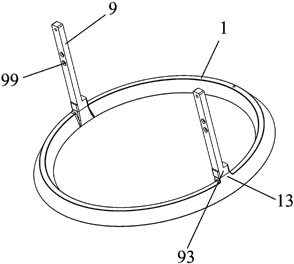
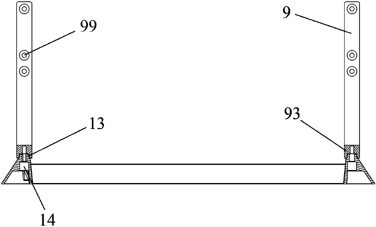
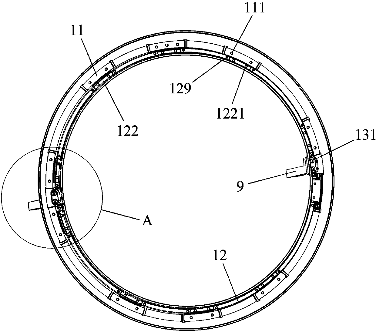
[0031] The ring-shaped rotating base of the preferred embodiment of the present invention is arranged at the lower part of the electronic equipment and is used to carry the electronic equipment. Please refer to Figure 1 to Figure 13 As shown, it includes: a base column 9, a base upper ring 1, a base lower ring mechanism (not marked), an annular cover mechanism (not marked); the lower part of the base upper ring 1 is provided with an annular accommodation chamber 10; The base column 9 is arranged on the upper ...


PUM


Abstract

The invention provides an annular rotating base and an electronic device. The annular rotating base comprises a base upper ring, a base stand column, a base lower ring mechanism and an annular cover plate mechanism, wherein an annular accommodating cavity is formed in the lower part of the base upper ring; the base stand column is arranged at the upper part of the base upper ring and used for being connected with the base upper ring and the electronic device; the base lower ring mechanism is arranged in the annular accommodating cavity, slidably connected with the base upper ring and used forsupporting the electronic device; and the annular cover plate mechanism is arranged at the bottom of the annular accommodating cavity, slidably connected with the base lower ring mechanism and used for preventing the base lower ring mechanism from being separated from the annular accommodating cavity. According to the annular rotating base, by designing the base into an annular shape, the base andthe whole machine rotate synchronously, the requirement that the annular base can rotate is satisfied, and the whole effect of the base and the whole machine is not affected during rotating.

Description

technical field [0001] The invention relates to the field of electronic equipment, in particular to an annular rotating base and electronic equipment. Background technique [0002] The base part of the electronic equipment includes a column and a base. Existing electronic equipment such as computers, televisions, and monitors can only rotate the column and the base is still, and the base column can only be placed in the middle. The single design has great limitations. When the whole machine rotates , the base does not move, the base forms a torsion angle with the complete machine, and the whole is uncoordinated. [0003] Therefore, the prior art still needs to be improved and developed. Contents of the invention [0004] In view of the deficiencies in the prior art above, the purpose of the present invention is to provide an annular rotating base and electronic equipment, so as to solve the problem that the existing electronic equipment can only stand still on the rotatin...

Claims


Application Information

Patent Timeline
Patent Type & Authority Patents(China)
IPC IPC(8): F16M11/08F16M11/22
CPCF16M11/08F16M11/2014
Inventor 胡灵超吴昌全徐千正
Owner SHENZHEN SKYWORTH RGB ELECTRONICS CO LTD
Why Eureka
Try Eureka