High-linearity and low-voltage phase interpolating circuit

A phase interpolation, low-voltage technology, applied in the direction of electrical components, single output arrangement, automatic power control, etc., to avoid insufficient voltage margin and eliminate nonlinear effects

Active Publication Date: 2018-02-13
北京华大九天科技股份有限公司
View PDF9 Cites 4 Cited by
  • Summary
  • Abstract
  • Description
  • Claims
  • Application Information

AI Technical Summary

Problems solved by technology

[0011] In order to solve the deficiencies in the prior art, the object of the present invention is to provide a high linearity low voltage applied to SERDES receiver clock data recovery which solves the linearity and low power supply voltage problems in the phase interpolation circuit (PI) phase interpolation circuit

Method used


Image

  • High-linearity and low-voltage phase interpolating circuit
  • High-linearity and low-voltage phase interpolating circuit
  • High-linearity and low-voltage phase interpolating circuit

Examples


Embodiment Construction

[0037] The preferred embodiments of the present invention will be described below in conjunction with the accompanying drawings. It should be understood that the preferred embodiments described here are only used to illustrate and explain the present invention, and are not intended to limit the present invention.

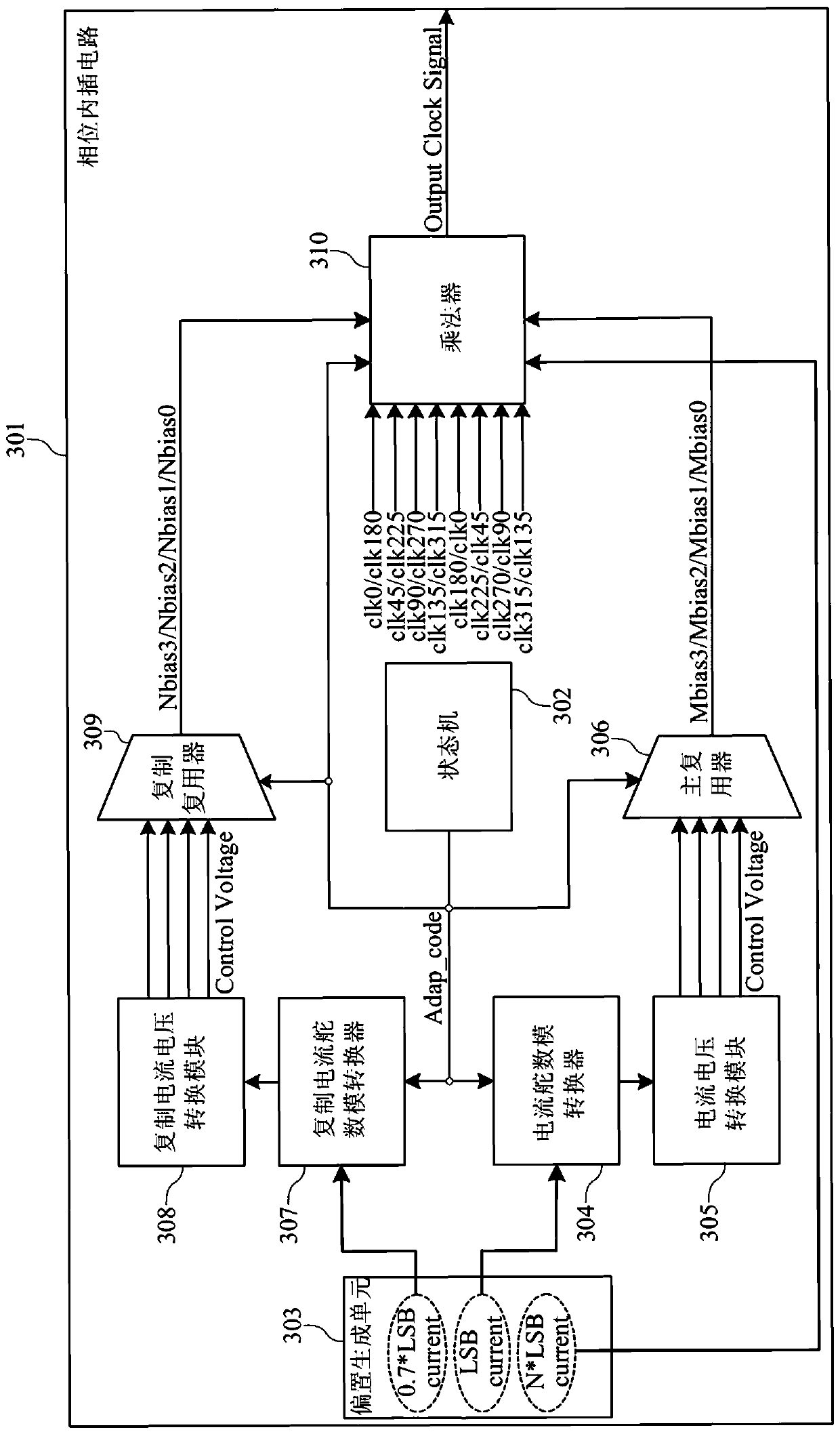
[0038] image 3 It is a schematic diagram of the overall structure of the high linearity low voltage phase interpolation circuit according to the present invention, such as image 3As shown, the high linearity low voltage phase interpolation circuit 301 of the present invention includes a state machine (Finite State Machine, FSM) 302, a bias generation unit (BiasGen) 303, a current steering digital-to-analog converter (Current Steering DAC) 304, Current-voltage conversion module (I2V module) 305, main multiplexer (Main MUX) 306, secondary current steering digital-to-analog converter (ReplicaCurrent Steering DAC) 307, secondary current-voltage conversion module (Repl...


PUM


Abstract

The invention provides a high-linearity and low-voltage phase interpolating circuit. The high-linearity and low-voltage phase interpolating circuit comprises a state machine, a biasing generation unit, a current-steering digital to analog converter, a voltage-current conversion module, a main multiplexer, a secondary current-steering digital to analog converter, a secondary voltage-current conversion module, a secondary multiplexer and a multiplier. The state machine is used for outputting a control code for controlling the current-steering digital to analog converter and the secondary current-steering digital to analog converter to output differential control current; the biasing generation unit is used for providing biasing current to the current-steering digital to analog converter, thesecondary current-steering digital to analog converter and the multiplier; the voltage-current conversion module and the secondary voltage-current conversion module are used for converting the differential control current to control voltage; the main multiplexer and the secondary multiplexer are controlled by the control code respectively and the control voltage is selected; the multiplier is used for outputting a phase interpolating circuit clock signal according to the control voltage and a clock signal output by a phase-locked loop. According to the high-linearity and low-voltage phase interpolating circuit provided by the invention, the linearity of the phase interpolating circuit can be improved and the non-linearity introduced by high-order harmonic waves is eliminated.

Description

technical field [0001] The invention relates to a serializer and a deserializer, in particular to a phase interpolation circuit in recovering clock data at the receiving end of the serializer and deserializer. Background technique [0002] In serial signal communication, with the continuous improvement of the transmission signal rate, higher design requirements are put forward for the clock and data recovery (CDR) circuit of the receiving end of SERDES (SERializer / DESerializer; serializer and deserializer) . Among them, a dual-loop (Dual Loop) structure clock data recovery (CDR) circuit combining a multi-phase clock output phase-locked loop (Phase Locked Loop, PLL) and a phase interpolator circuit (Phase Interpolator, PI) is more and more used. . [0003] Among them, the design principle of the phase interpolation circuit (PI) is based on the fact that any component whose phase is between the quadrature signals can be approximately represented by a linear combination of th...

Claims


Application Information

Patent Timeline
Patent Type & Authority Applications(China)
IPC IPC(8): H03L7/081H03K5/13
CPCH03K5/13H03L7/0814
Inventor 徐震唐重林刘寅
Owner 北京华大九天科技股份有限公司
Why Eureka
Try Eureka