
Sliding mode control method and control device for tension of tension roll strip steel

A control method and tension control technology, applied in the direction of mechanical pressure/force control, adaptive control, general control system, etc., can solve the problems of unsatisfactory control effect and low control precision

Active Publication Date: 2019-01-11
LIAONING UNIVERSITY OF TECHNOLOGY
View PDF6 Cites 4 Cited by
  • Summary
  • Abstract
  • Description
  • Claims
  • Application Information

AI Technical Summary

Problems solved by technology

Most of the existing strip tension control devices adopt PID control algorithm, the control precision is low, and the control effect is not ideal

Method used


Image

  • Sliding mode control method and control device for tension of tension roll strip steel
  • Sliding mode control method and control device for tension of tension roll strip steel
  • Sliding mode control method and control device for tension of tension roll strip steel

Examples


Embodiment

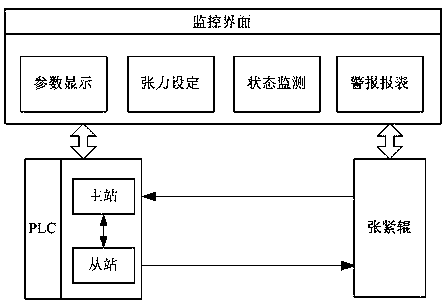
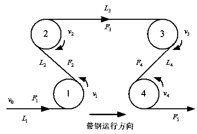
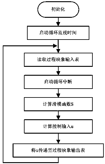
[0074] Such as Figure 1-3 Shown, the sliding mode control method of a kind of tension roller strip steel tension of the present invention comprises the following steps:

[0075] Step 1. Tension roller strip tension modeling

[0076] (1) tension roller structure

[0077] The invention establishes a tension roller strip steel tension control model by taking a 4-axis tension roller composed of 4 driving rollers as an example. According to the order in which the steel strip passes through each roller, each drive roller is defined as No. 1, No. 2, No. 3, and No. 4. Among them, No. 1 roller and No. 4 roller rotate counterclockwise, No. 2 roller and No. 3 roller rotate clockwise, v 0 is the upstream strip speed of the tension roll, v 1 , v 2 , v 3 , v 4 are the rotational linear speeds of each drive roller, respectively. Among them, v 0 The size of vi is determined by the upstream production process and can be detected by measuring tools, which is a known parameter; the siz...


PUM


Abstract

The invention provides a sliding mode control method and control device for the tension of a tension roll strip steel, and belongs to the field of the industrial automation. The method comprises the following steps of: step 1: modeling the tension of the tension roll strip steel; step 2: designing the sliding mode control method of the tension roll strip steel. Compared with a traditional PID control method, the sliding mode control method of the invention can effectively overcome control difficulties such as the non-linear of the tension of the tension roll strip steel, and the unknown external disturbance. The invention relates to a sliding mode control device for the tension of a tension roll strip steel. The control device selects a Siemens S7-300 series PLC (CPU model 315-2DP) as a master station, and selects a distributed I / O ET200S (CPU model IM151-7) with own CPU as a slave station. The master and slave stations communicate via the Profibus-DP fieldbus. The hardware design andthe software design of the control device are completed.

Description

technical field [0001] The invention designs a tension roller strip steel tension sliding mode control method and a control device, belonging to the field of industrial automation. Background technique [0002] In the process of metallurgical production, the precise control of tension roller strip tension is the key factor to ensure the quality of strip products and improve the efficiency of strip production. Most of the existing strip steel tension control devices adopt PID control algorithm, which has low control precision and unsatisfactory control effect. Contents of the invention [0003] The purpose of the present invention is to design a sliding mode control method of tension roller strip tension, compared with the traditional PID control method, the sliding mode control method of the present invention can effectively overcome the nonlinearity of tension roller strip tension , unknown external interference and other control difficulties; another object of the prese...

Claims


Application Information

Patent Timeline
IPC IPC(8): G05D15/01G05B13/04
CPCG05B13/042G05D15/01
Inventor 白锐祁学鹏王贺彬孙丽颖
Owner LIAONING UNIVERSITY OF TECHNOLOGY
Learn More