Wire tensioning device control device

A control device and wire tightening technology, applied in the direction of overhead lines/cable equipment, etc., can solve problems such as low operating efficiency, achieve the effects of improving efficiency, saving operating field space, and improving operating efficiency

Active Publication Date: 2018-02-16
NAGAKI SEIKI CO LTD
View PDF8 Cites 1 Cited by
  • Summary
  • Abstract
  • Description
  • Claims
  • Application Information

AI Technical Summary

Problems solved by technology

In such a limited space, it is necessary to separately operate a plurality of machines for work as described above, and there is a problem of low work efficiency.

Method used


Image

  • Wire tensioning device control device
  • Wire tensioning device control device
  • Wire tensioning device control device

Examples


Embodiment Construction

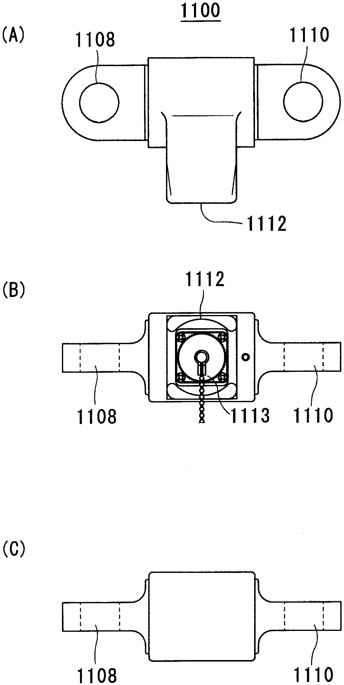
[0034] Before describing the control device of the thread tensioning device of the present invention, at first, refer to Figure 5 and Figure 6 One embodiment of the thread tensioning device controlled by the control device of the thread tensioning device of the present invention will be described. Also, subsequently, refer to image 3 An embodiment of a tension gauge (load sensor) that measures the tension of an electric wire or the like and transmits an electric signal value corresponding to the tension to the control device of the wire tensioning device of the present invention will be described.

[0035] (Structure of the tensioning device)

[0036] Figure 5 It is an exploded perspective view showing one embodiment of the thread tensioning device controlled by the control device of the thread tensioning device of the present invention. in addition, Figure 6 It is a front sectional view of one embodiment of the thread tensioning device controlled by the control devi...


PUM


Abstract

Provided is a wire tensioning device control device that improves the efficiency of work for providing an overhead wire and the like in a tensioned state. The wire tensioning device control device 2000 controls a wire tensioning device for providing an overhead wire and the like in a tensioned state and has one rotational drive mechanism control means 2020, a forward/reverse operation switching means 2040 for the rotational drive mechanism control means 2020, and a tension display means 2060 for displaying tension obtained by the wire tensioning device, which are provided in an integrally arranged state. The wire tensioning device control device 2000 is electrically connected to a tension meter, controls the wire tensioning device, obtains the value corresponding to the tension occurring in the overhead wire from the tension meter, and displays the tension.

Description

technical field [0001] The present invention relates to a control device for controlling a wire tensioning device, and more particularly to a control of a wire tensioning device capable of stretching a free end of a stringing wire or the like horizontally or laterally and holding it on the utility pole side, for example, in stringing work, etc. device. Background technique [0002] Conventionally, erection work such as wirework generally required a plurality of devices. [0003] For example, in the erection work of electric wires, tension gauges are used to measure tension. In the stringing work of electric wires and the like, sag is considered as the height between the supporting point of the electric wire and the lowest point of the curve formed by the electric wire. By adopting a large sag, the tensile force on the electric wire itself can be reduced to improve safety, but if the sag is too large, supports such as iron towers have to be increased. Therefore, in order t...

Claims


Application Information

Patent Timeline
Patent Type & Authority Applications(China)
IPC IPC(8): H02G1/04
CPCH02G1/04
Inventor 野川保次
Owner NAGAKI SEIKI CO LTD
Why Eureka
Try Eureka