Connecting device

A connecting device and connecting head technology, which is applied in the direction of supporting machines, mechanical equipment, machine tables/supports, etc., can solve problems such as short service life, inconvenient use, and low safety, and achieve high safety, reasonable design, and easy operation. simple effect

Inactive Publication Date: 2016-03-16
QINGDAO HANGXIN ELECTROMECHANICAL TECH CO LTD
View PDF0 Cites 0 Cited by
  • Summary
  • Abstract
  • Description
  • Claims
  • Application Information

AI Technical Summary

Problems solved by technology

[0002] In the past, in this kind of connecting body in the factory, the inner and outer connecting bodies were directly connected, and the service life was short, the quality was poor, the safety was low, and it was very inconvenient to use.

Method used


Image

  • Connecting device

Examples


Embodiment Construction

[0010] The present invention will be further described below in conjunction with accompanying drawing:

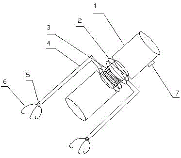
[0011] As shown in the figure, a connecting device is mainly composed of a connecting head 1, an annular connecting body 2, a spring 3, a connecting rod 4, a connecting shaft 5, a hook 6, and a tension monitor 7. It is characterized by:

[0012] The connecting head 1 is connected to the spring 3, the spring 3 is in the middle of the connecting head 1, the annular connecting body 2 is sleeved on the periphery of the spring 3, and the connecting rod 4 is connected to the annular connecting body 2 The connecting shaft 5 is connected to the connecting rod 4, the hook 6 is connected to the connecting shaft 5, and the tension monitor 7 is installed on the connecting head 1.

[0013] The function of the connector 1 is to connect external objects, the function of the annular connector 2 is to facilitate the rotation of the connector 1, the function of the spring 3 is to relieve th...


PUM


Abstract

The invention relates to a connecting device. The connecting device is mainly composed of a connecting head, an annular connecting body, a spring, a connecting rod, a connecting rotating shaft, a hook and a tension monitor. The connecting device has the beneficial effects of being easy to operate, convenient to use, reasonable in design and high in safety, and meanwhile tension of the connecting device can be monitored.

Description

technical field [0001] The invention relates to a connecting body, in particular to a connecting device. Background technique [0002] In the past, in this kind of connector in the factory, the inner and outer connectors were directly connected, and the service life was short, the quality was poor, the safety was low, and it was very inconvenient to use. Contents of the invention [0003] In order to solve the above problems, the object of the present invention is to provide a connecting device that is easy to manufacture and easy to use. [0004] In order to achieve the above object, a connecting device of the present invention is mainly composed of a connecting head, an annular connecting body, a spring, a connecting rod, a connecting shaft, a hook, and a tension monitor, and is characterized in that: [0005] The connecting head is connected to the spring, the spring is in the middle of the connecting head, the annular connecting body is sleeved on the periphery of the...

Claims


Application Information

Patent Timeline
Patent Type & Authority Applications(China)
IPC IPC(8): F16M13/02F16M11/06
Inventor 冷广军
Owner QINGDAO HANGXIN ELECTROMECHANICAL TECH CO LTD
Why Eureka
Try Eureka