Eureka AIR delivers breakthrough ideas for toughest innovation challenges, trusted by R&D personnel around the world.

An anti-off clamp

A clamp and anti-dropping technology, applied in the direction of pliers, manufacturing tools, etc., can solve the problems of unable to clamp the object to be clamped, unable to ensure the clamping strength, etc., and achieve the effect of simple structure, easy function, and firm clamping.

Active Publication Date: 2019-11-01
中科数字健康科学研究院(南京)有限公司
View PDF5 Cites 0 Cited by
  • Summary
  • Abstract
  • Description
  • Claims
  • Application Information

AI Technical Summary

Problems solved by technology

[0002] Existing clamps usually have a single scissor-like structure, which clamps the clamped object through the grip of the hand, but such clamps often cannot clamp the clamped object particularly stably, and the hand is slightly loose Clamping strength cannot be guaranteed after opening

Method used

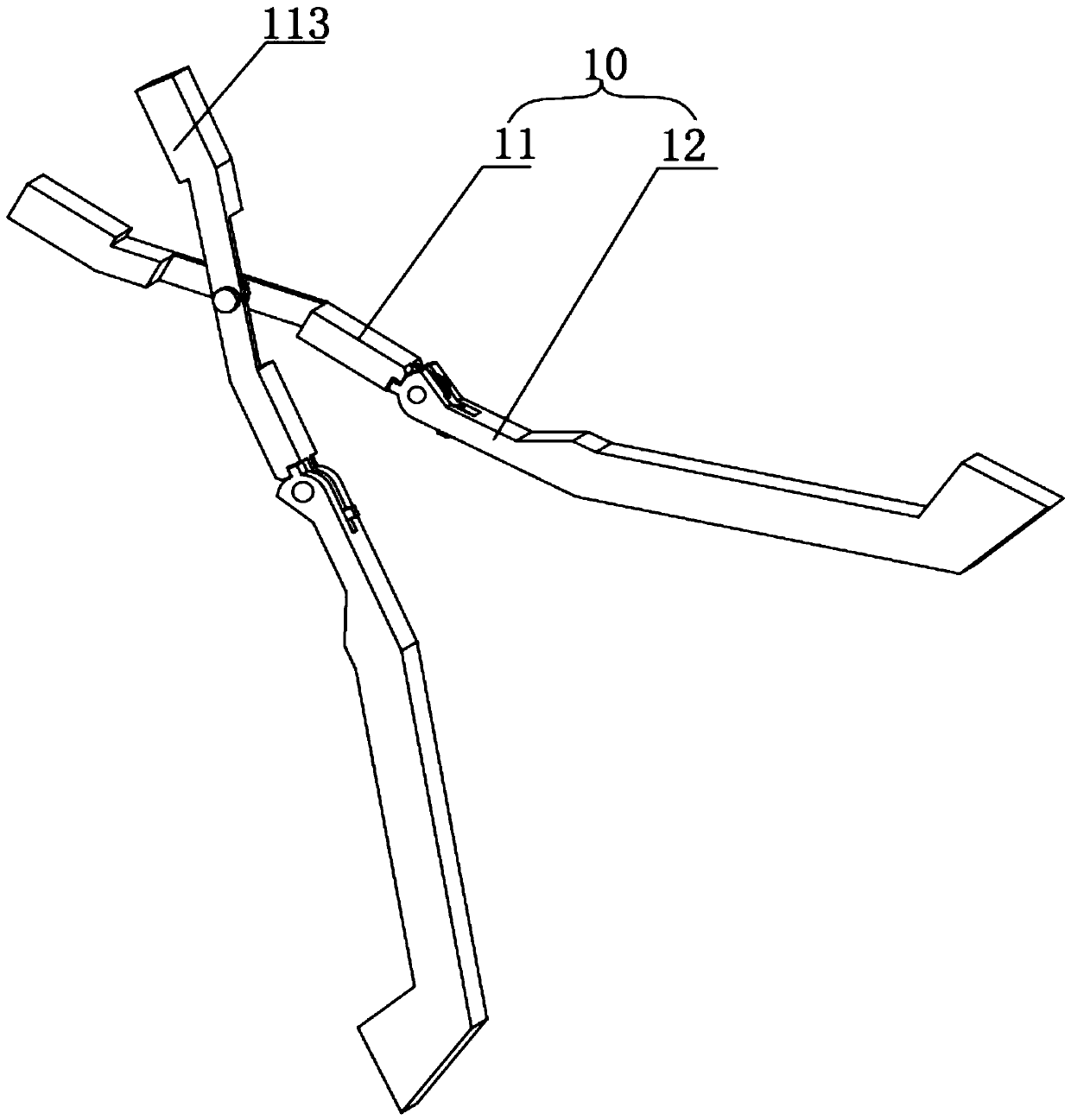

Image

  • An anti-off clamp
  • An anti-off clamp
  • An anti-off clamp

Examples


Embodiment Construction

[0038] In order to make the purpose, technical solutions and advantages of the embodiments of the present invention clearer, the technical solutions in the embodiments of the present invention will be clearly and completely described below in conjunction with the accompanying drawings in the embodiments of the present invention. Obviously, the described embodiments It is some embodiments of the present invention, but not all of them. Based on the implementation manners in the present invention, all other implementation manners obtained by persons of ordinary skill in the art without creative efforts fall within the protection scope of the present invention. Accordingly, the following detailed description of the embodiments of the invention provided in the accompanying drawings is not intended to limit the scope of the claimed invention, but merely represents selected embodiments of the invention. Based on the implementation manners in the present invention, all other implement...


PUM


Abstract

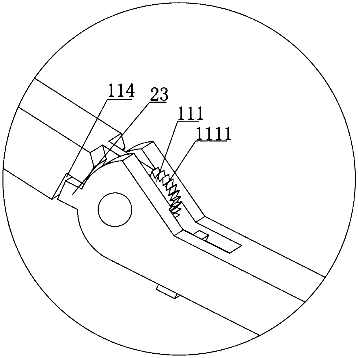
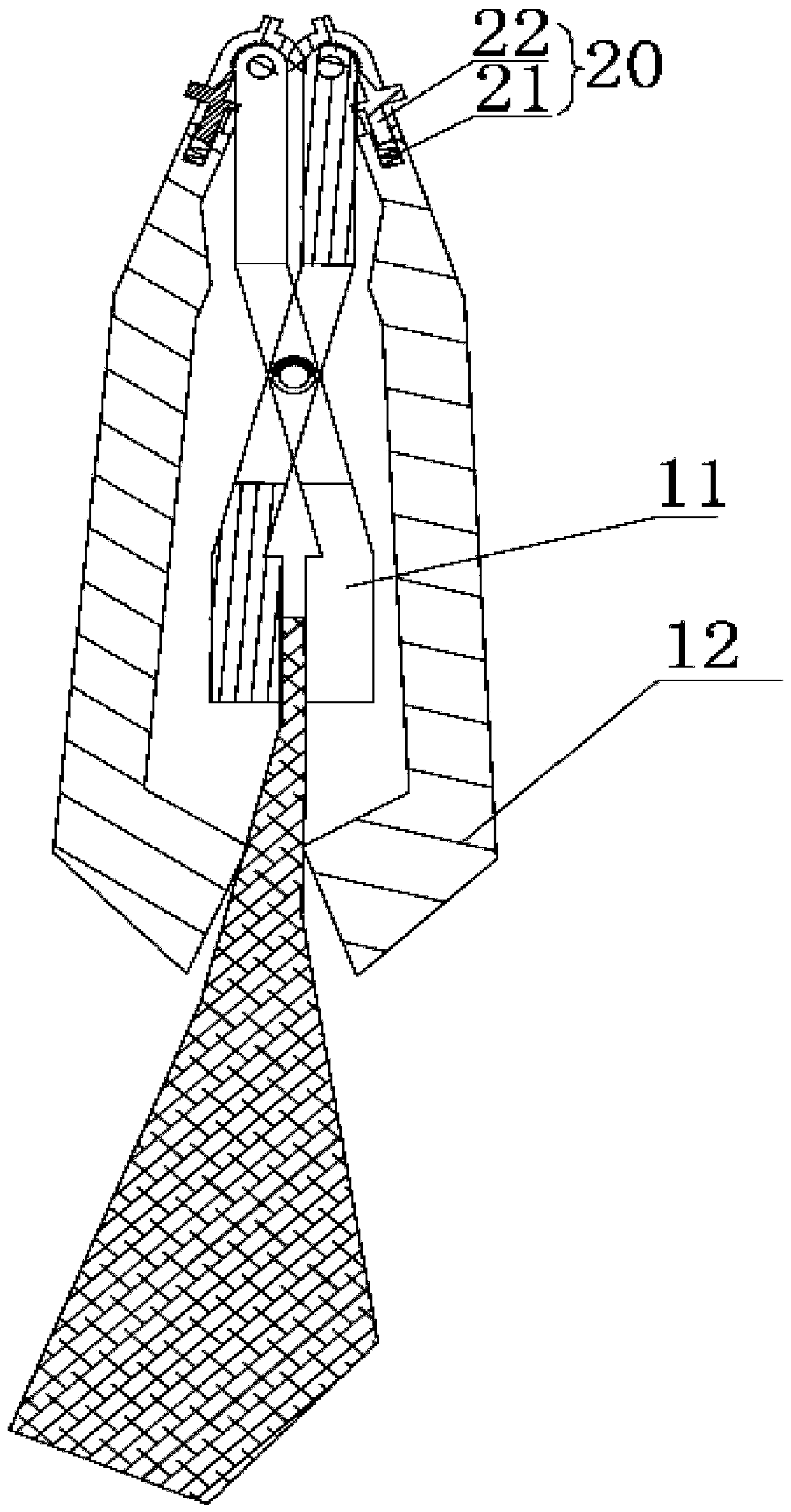
The invention discloses an anti-disengaging clamp which comprises two clamping units, wherein the two clamping units are matched and are of the same structure. The clamping units comprise clamping portions and reinforcing portions which are hinged to each other, wherein the clamping portions are hinged to achieve primary clamping of an object to be clamped. The length of the reinforcing portions is larger than that of the clamping portions, and one ends of the two reinforcing portions are respectively hinged to the tail ends of the two clamping portions. The two reinforcing portions can rotatetowards the front ends of the two clamping portions respectively so as to realize secondary clamping of the object to be clamped. Elastic limiting pieces are arranged in the reinforcing portions. Theelastic limiting pieces comprise springs and limiting pieces which are fixedly connected, the other ends of the springs are fixed in the reinforcing portions, and limiting portions are arranged at the tail end of the clamping portions. When the springs are compressed, the limiting portions and the reinforcing portions can rotate at one ends of the clamping portions. The anti-disengaging clamp hasthe advantages that the labor is saved, the clamping strength can be guaranteed in real time, the clamping is firm, and the placing size is small.

Description

technical field [0001] The invention relates to the technical field of medical equipment, in particular to an anti-off clamp. Background technique [0002] Existing clamps usually have a single scissor-like structure, which clamps the clamped object through the grip of the hand, but such clamps often cannot clamp the clamped object particularly stably, and the hand is slightly loose Clamping strength cannot be guaranteed after opening. Contents of the invention [0003] In view of the technical problems existing in the background technology that the object to be clamped cannot be firmly clamped and is inconvenient to use, the purpose of the present invention is to overcome the shortcomings of the prior art and provide a labor-saving, real-time guaranteed clamping strength and firm clamping. And place a small anti-off clamp. [0004] In order to solve the problems of the technologies described above, the present invention adopts the following technical measures: [0005]...

Claims


Application Information

Patent Timeline
Patent Type & Authority Patents(China)
IPC IPC(8): B25B7/00
CPCB25B7/00
Inventor 张平
Owner 中科数字健康科学研究院(南京)有限公司
Why Eureka
Eureka Blog
Learn More