Communication cavity air guide and pressure grout supply method used for sleeve grouting connection

A sleeve grouting and Unicom technology, applied to ceramic molding machines, manufacturing tools, etc., can solve problems such as insufficient air removal, and achieve the effects of improving construction efficiency and simplifying work processes

Active Publication Date: 2018-02-23
JIANYAN DETECTION GRP CO LTD +2
View PDF4 Cites 4 Cited by
  • Summary
  • Abstract
  • Description
  • Claims
  • Application Information

AI Technical Summary

Problems solved by technology

[0005] The purpose of the present invention is to overcome the deficiencies of the prior art, and provide a method for conducting air in the connecting cavity and pressure grouting for sleeve grouting connection. This method effe

Method used


Image

  • Communication cavity air guide and pressure grout supply method used for sleeve grouting connection
  • Communication cavity air guide and pressure grout supply method used for sleeve grouting connection
  • Communication cavity air guide and pressure grout supply method used for sleeve grouting connection

Examples


Embodiment 1

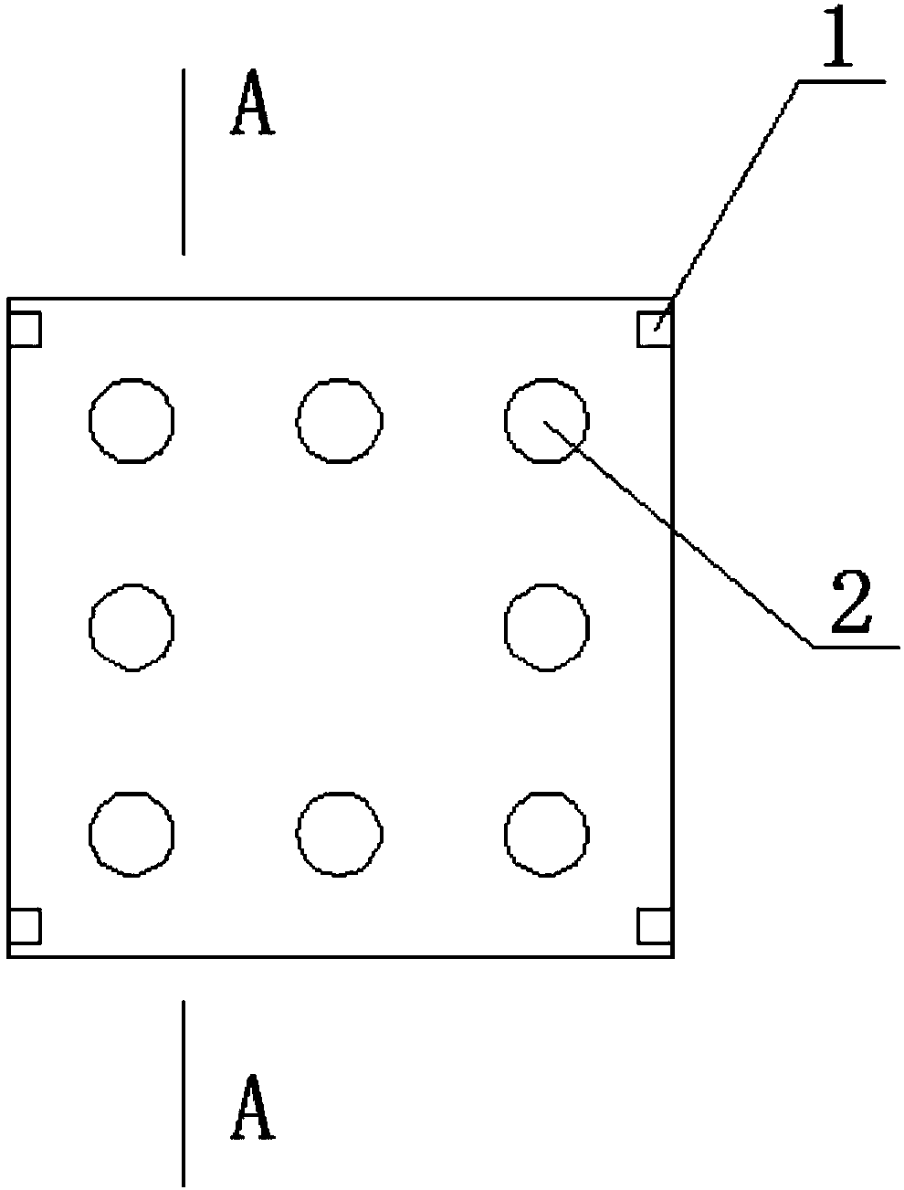
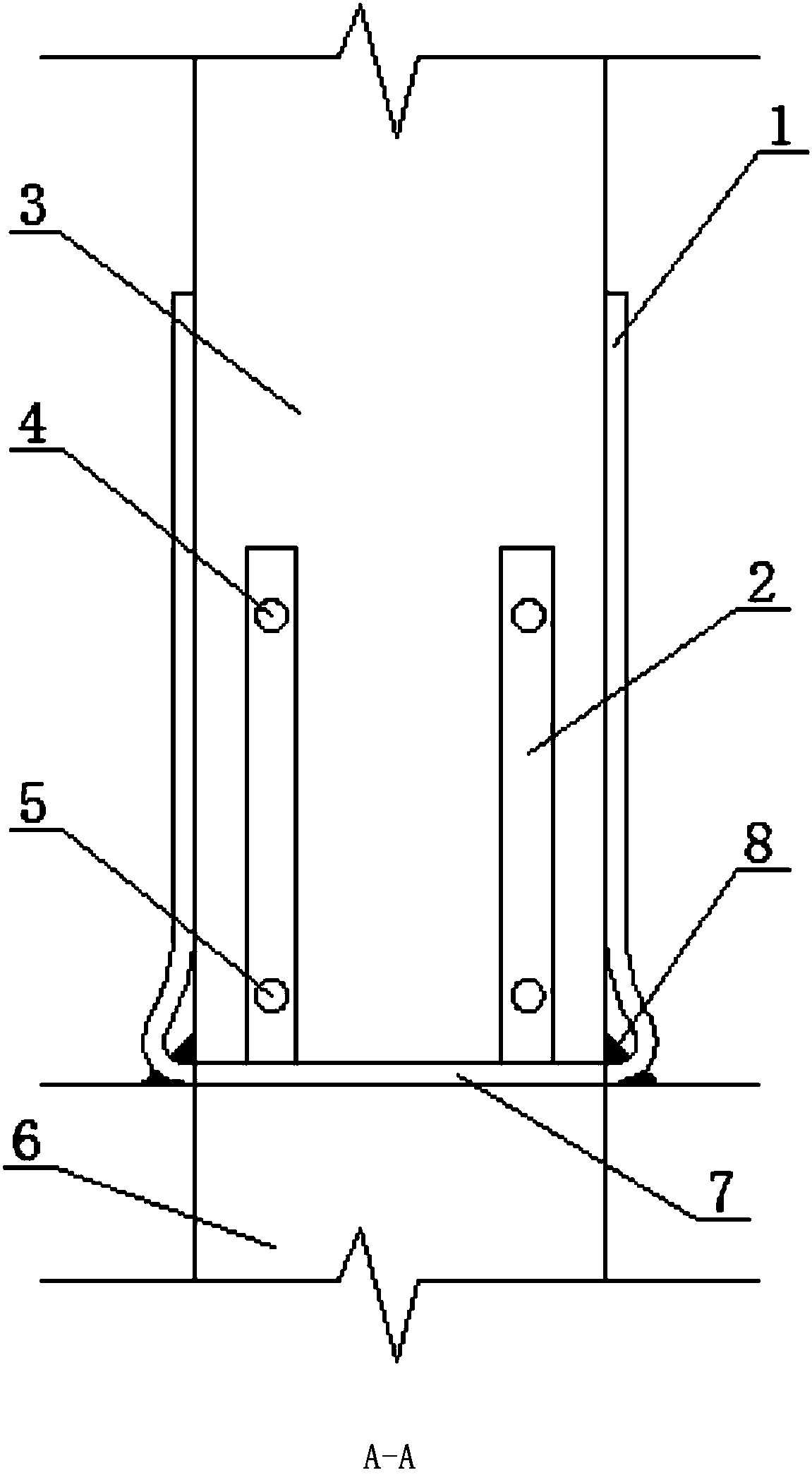
[0028] The prefabricated concrete components or the upper and lower section prefabricated components mentioned in this application can be prefabricated concrete columns or prefabricated concrete walls. In this embodiment, taking the connection process of the upper and lower prefabricated components of the precast concrete column as an example, the air guiding and pressure grouting method of the connecting cavity of the present invention is specifically described. For specific content, refer to figure 1 , figure 2 shown.

[0029] The operation process of the present embodiment is as follows.

[0030] 1. Preparation of grouting material:

[0031] The mixing water of the grouting material shall be potable water, and other water shall comply with the provisions of the "Standard for Concrete Mixing Water" (JGJ63-2006).

[0032] The ambient temperature should meet the requirements of the instruction manual of the grouting material product. When the temperature is too high, the ...

Embodiment 2

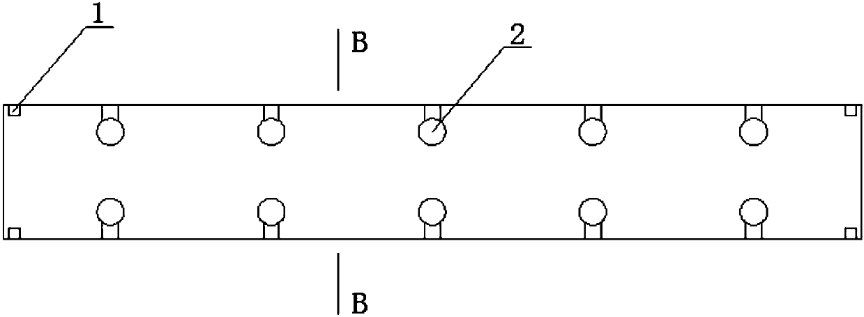
[0047] The difference between this embodiment and the first embodiment is that the concrete components for construction are replaced by prefabricated concrete columns and prefabricated concrete walls. For details, see image 3 , Figure 4 shown. The prefabricated concrete wall is divided into an upper prefabricated wall 8 and a lower prefabricated wall 9 .

[0048] The difference when it is applied to a prefabricated concrete wall is that when the length of the prefabricated wall is longer, it is necessary to divide the joint communication cavity 7 into bins and use segmented grouting. At this time, the position of the air guiding hose 1 is correspondingly arranged at the four corners of the connecting cavity 7 in different sections of the seam, and the process of the connecting cavity air guiding and pressure grouting in the first embodiment is repeated respectively.


PUM

PropertyMeasurementUnit
Compressive strengthaaaaaaaaaa

Abstract

The invention discloses a communication cavity air guide and pressure grout supply method used for sleeve grouting connection. A plurality of air guide hoses are led from a joint communication cavity,one ends of the air guide hoses are arranged at the four corners of the joint communication cavity, the other ends of the air guide hoses are led out of the joint communication cavity and arranged onthe side face of an upper section of a prefabricated part in the vertical direction in an attached manner, and the other ends of the air guide hoses are higher than the upper end faces of steel bar sleeves. Because the liquid levels in the air guide hoses are higher than the steel bar sleeves, pressure grout supply can be carried out on the interiors of the steel bar sleeves, and it is more convenient for an operator to judge the current grouting progress and situation according to the liquid level changes in the air guide hoses and make adjustment in real time. According to the communicationcavity air guide and pressure grout supply method used for sleeve grouting connection effectively, the problem that air is prone to not being discharged adequately in the prior art is solved, meanwhile the grout supply process is simplified, the connection quality of a precast concrete member is improved, and the working efficiency is improved.

Description

technical field [0001] The invention relates to the technical field of prefabricated concrete construction engineering, in particular to the connection technology of upper and lower prefabricated concrete columns or walls. Background technique [0002] In the prefabricated concrete construction project, in the process of connecting the vertically arranged upper and lower sections of precast concrete columns or walls (collectively referred to as "prefabricated components"), it is necessary to reserve plug-in steel bars for connection on the concrete end faces of the lower prefabricated components. After being connected with the hollow steel sleeves at the corresponding positions of the prefabricated components in the upper section, cement-based grouting materials are used for connection. [0003] In the prior art, the method for grouting connection of steel bar sleeves is as follows: first, the upper and lower sections of prefabricated components are separately manufactured. ...

Claims


Application Information

Patent Timeline
IPC IPC(8): B28B21/04
CPCB28B21/04
Inventor 李长太袁慎明桂苗苗邱聪李晓斌
Owner JIANYAN DETECTION GRP CO LTD
Why Eureka
Try Eureka