
A comb-tooth plate stacker

A stacker and comb technology, applied in the field of comb-type plate stackers, can solve the problems of low production efficiency, limited service area, low adaptability to the variety of loaded plate specifications, etc., and achieve low cost and production efficiency. high effect

Active Publication Date: 2019-03-19
DALIAN HUARUI HEAVY IND GRP CO LTD
View PDF6 Cites 0 Cited by
  • Summary
  • Abstract
  • Description
  • Claims
  • Application Information

AI Technical Summary

Problems solved by technology

[0002] The plate stacker in the prior art has low adaptability to the diversity of loaded plate specifications. When the plate has a large span in shape and size, especially a plate with a large width and thickness span, and the stacked plate specifications are not uniform at the same time, the stacker will Unable to meet work requirements, limited service area, similar steel plate finished product warehouse needs to store multi-standard steel plates, requires intelligent access, high production efficiency, the existing plate stacker can not meet the requirements, can only use general finished product warehouse, through manual operation Management of outgoing and incoming steel plates results in high labor costs and low production efficiency

Method used


Image

  • A comb-tooth plate stacker
  • A comb-tooth plate stacker
  • A comb-tooth plate stacker

Examples


Embodiment 1

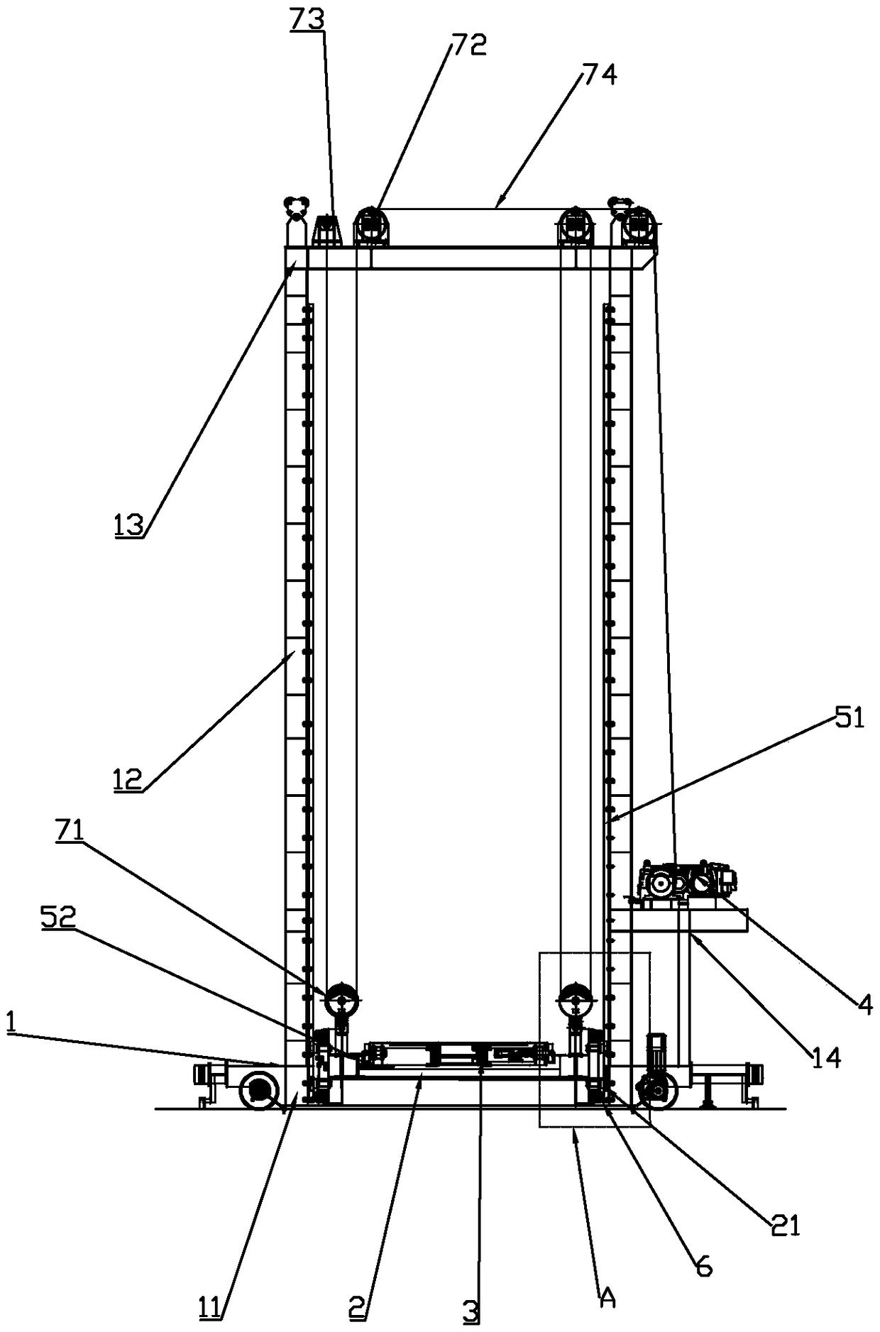
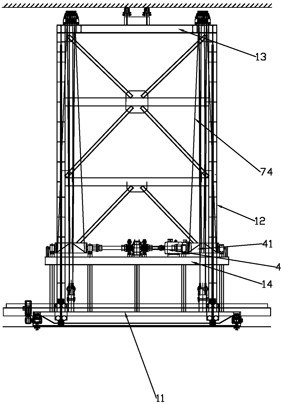
[0037] Such as Figure 1 to Figure 8 As shown, a comb-tooth plate stacker includes a main structure 1, a lifting trolley 2, a transport trolley 3 and a lifting mechanism 4,

[0038] The main structure 1 includes a bottom plate 11, a column 12, a top plate 13 and a support frame 14. The lower ends of the four columns 12 are fixed to the upper end of the bottom plate 11 in a rectangular shape, and the inside of the columns 12 are fixedly connected to the first guide rail 51 by bolts. The lower end of the top plate 13 is fixed to the upper end of the column 12, the lower end of the support frame 14 is fixed to the right side of the bottom plate 11, and the left end of the support frame 14 is fixed to the bottom of the column 12 on the right side;

[0039] The left and right ends of the lifting trolley 2 are fixedly provided with vertically symmetrical first guide wheels 6 that are rollingly connected with the first guide rail 51, and the vertically symmetrical first guide wheels ...

Embodiment 2

[0058] Such as Figure 9 to Figure 11 As shown, the difference between this embodiment and Embodiment 1 is that it also includes four sets of operating mechanisms 8 fixed to the lower end of the bottom plate 11 in a rectangular shape, and the operating mechanisms 8 include a first drive motor 81, an intersecting axis gearbox 82 and a bottom guide wheel 83, the bottom guide wheel 83 is connected with the first drive motor 81 through the intersecting shaft gearbox 82.

[0059] The running mechanism 8 is rollingly connected with the bottom guide rail 101 on the ground through the bottom guide wheel 83, so that the comb-tooth plate stacker can move in the warehouse.

[0060] Further, in the above technical solution, the top guide device 9 is symmetrically arranged at the left and right ends of the middle part of the top plate 13, and the top guide device 9 includes a connecting support 91, a guide wheel connecting rod 92 and a top guide wheel 93. The lower end of the support 91 i...


PUM


Abstract

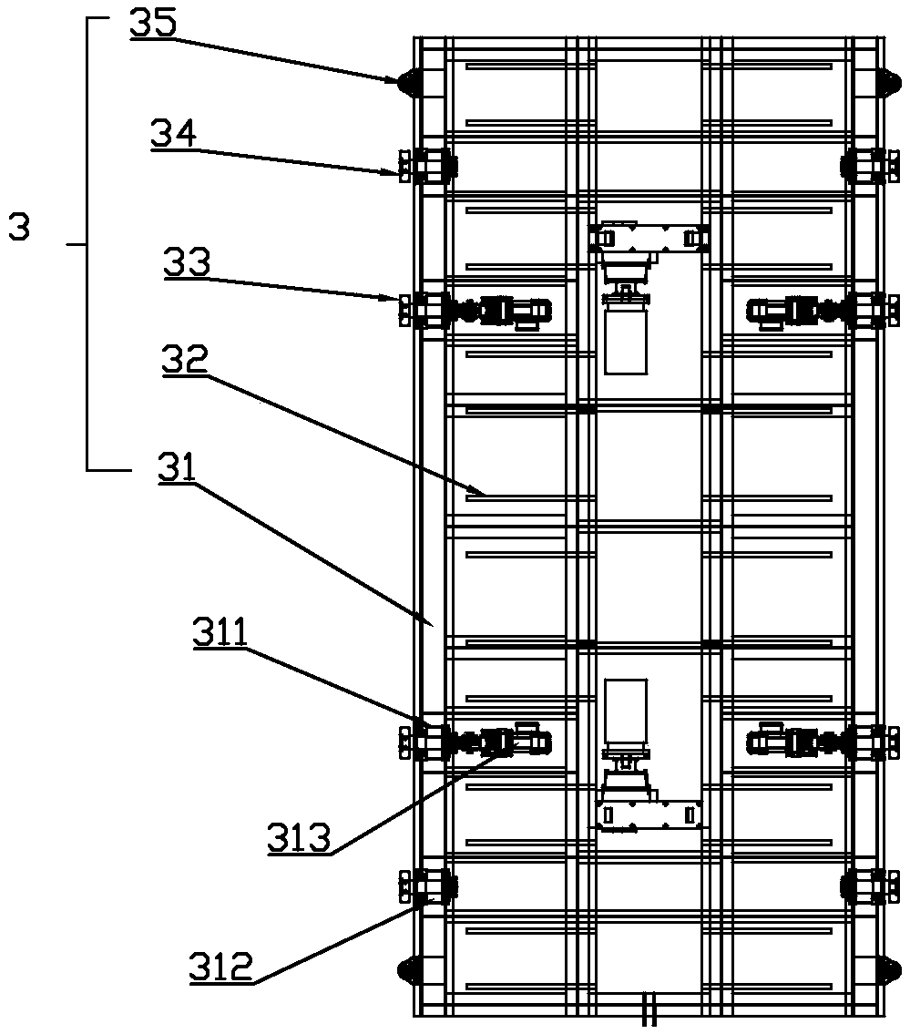
The invention discloses a comb-tooth-type plate stacking machine. The comb-tooth-type plate stacking machine comprises a main body structure, a lifting trolley, a carrying trolley and a lifting mechanism. The main body structure comprises a bottom plate, vertical posts, a top plate and a supporting frame. The left end and the right end of the lifting trolley are fixedly provided with first guide wheels which are vertically symmetrical and are in rolling connection with first guide rails, and L-shaped guide rails which are symmetrical in a left-right mode are fixedly arranged in the middle of the lifting trolley from front to back. The carrying trolley comprises a trolley frame, a comb tooth lifting mechanism, driving wheels, driven wheels and second guide wheels, wherein the driving wheelsand the driven wheels are in rolling connection with the upper ends of the L-shaped guide rails, the second guide wheels are in rolling connection with the inner sides of the L-shaped guide rails, and the comb tooth lifting mechanism comprises driving devices and a comb tooth structure. The lifting mechanism is fixed to the upper end of the supporting frame. The comb-tooth-type plate stacking machine is suitable for intelligent stereoscopic storage of plates in different specifications.

Description

technical field [0001] The invention belongs to the technical field of hoisting and transporting machinery, and in particular relates to a comb-tooth plate stacker. Background technique [0002] The sheet stacker in the prior art has low adaptability to the diversity of sheet material specifications. When the sheet material has a large span, especially a sheet with a large width and thickness span, and the stacked sheet specifications are not uniform at the same time, the stacker will Unable to meet the work requirements, the service area is limited, similar steel plate finished product warehouses need to store multi-standard steel plates, require intelligent access, high production efficiency, the existing plate stacker can not meet the requirements, can only use the general finished product warehouse, through manual operation The management of outgoing and incoming steel plates results in high labor costs and low production efficiency. Therefore, the market is in urgent n...

Claims


Application Information

Patent Timeline
Patent Type & Authority Patents(China)
IPC IPC(8): B66F9/07B66F9/075B66F9/12B66F9/19B66F9/20
CPCB66F9/07B66F9/075B66F9/127B66F9/19B66F9/20
Inventor 韩再学李绍山刘晓飞张城玮衣启青李洋
Owner DALIAN HUARUI HEAVY IND GRP CO LTD
Learn More