
Vertical axis-type hydroelectric power generating device and vertical axis-type hydroelectric power generating unit

A technology of hydroelectric power generation device and vertical axis, which is applied in the direction of hydropower generation, water wheel, machine/engine, etc. It can solve the problems of hindering popularization, huge initial cost and maintenance cost, economic rationality, maintenance cost of dust removal device, etc., and achieves the goal of setting Effects of cost suppression and sufficient output characteristics

Active Publication Date: 2018-02-23
THK CO LTD
View PDF9 Cites 0 Cited by
  • Summary
  • Abstract
  • Description
  • Claims
  • Application Information

AI Technical Summary

Problems solved by technology

However, when these waterwheels are to be installed in existing waterways, a large-scale waterway improvement project is required to prevent water from overflowing from the waterways, and therefore, there are many restrictions on the installation places of hydroelectric power plants.
In addition, in terms of the characteristics of the waterwheel, since the garbage flowing in the waterway is accumulated in the waterwheel, a dust removal device and a huge maintenance cost are also required.
That is to say, there are factors hindering the popularization of conventional hydroelectric power generation devices from the viewpoint of economical rationality such as huge initial costs and maintenance costs.

Method used


Image

  • Vertical axis-type hydroelectric power generating device and vertical axis-type hydroelectric power generating unit
  • Vertical axis-type hydroelectric power generating device and vertical axis-type hydroelectric power generating unit
  • Vertical axis-type hydroelectric power generating device and vertical axis-type hydroelectric power generating unit

Examples


Embodiment Construction

[0030] Hereinafter, preferred embodiments for carrying out the present invention will be described using the drawings. It should be noted that the following embodiments are not intended to limit the invention of each technical solution, and combinations of features described in the embodiments are not necessarily essential to the solution means of the invention.

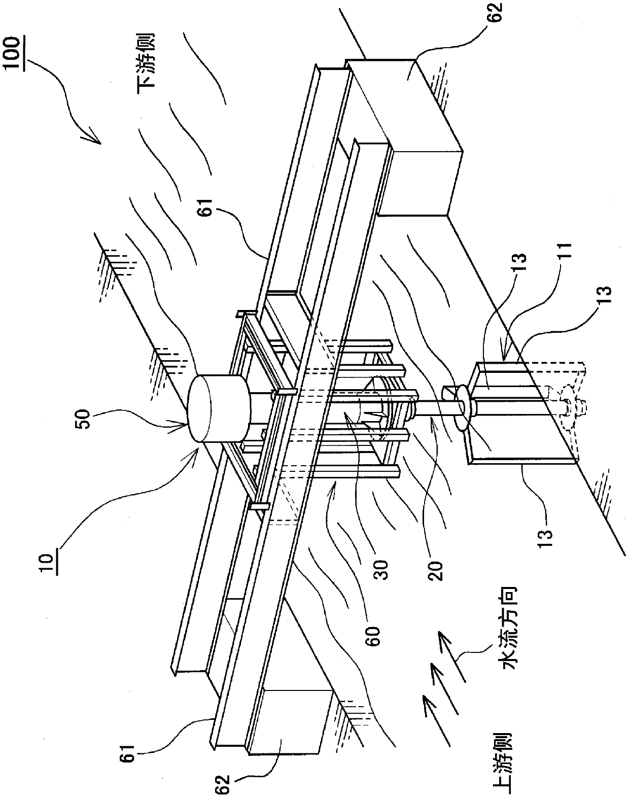
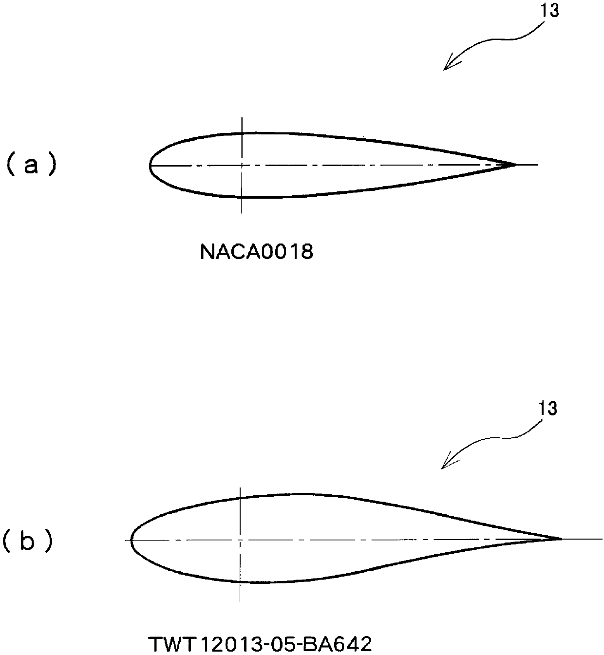
[0031] First, an example of the overall configuration of the vertical axis type hydroelectric power generation unit 100 according to the present embodiment will be described. here, figure 1 It is an external perspective view showing the overall configuration of the vertical axis type hydroelectric power generation unit according to the present embodiment, figure 2 It is a figure which exemplifies the shape of an airfoil applicable to the vertical-axis hydroelectric power generation apparatus which concerns on this embodiment.

[0032] The vertical-axis hydroelectric power generation device 10 according to the pres...


PUM


Abstract

This vertical axis-type hydroelectric power generating device (100) is provided with: a power generator (50) that receives a rotary driving force from a water flow to thereby generate electric power;a vertical rotating shaft (20) that is rotatably coupled to the power generator (50) and is installed so as to be suspended downward in the vertical direction; and a plurality of blades (13) disposedalong the circumferential direction on the periphery of the vertical rotating shaft (20) at approximately equal angle intervals. The plurality of blades (13) are formed so as to extend in the verticaldirection and are formed as straight wings each having a cross-sectional shape comprising a wing-like shape, and the plurality of blades (13) are configured from at most five blades when viewed fromthe bottom surface. According to such a configuration, it is possible to provide an unprecedented vertical axis-type hydroelectric power generating device which is capable of suppressing an excitationforce (fatigue load) generated by the effect of the water flow to a low level while ensuring sufficient output characteristics, and is further capable of suppressing the mass of the structural body and the installation cost of the entire device to a minimum.

Description

technical field [0001] The present invention relates to a vertical axis hydroelectric power generation device and a vertical axis hydroelectric power generation unit. Background technique [0002] Conventionally, there is known a hydroelectric power generation device that rotates blades of a waterwheel by using a water flow, and transmits the rotational motion to a generator to generate electric power. In the conventional small-sized hydroelectric power generation devices, the "fall type" that intercepts the waterway to generate electricity, and the "barrel rotor (Savonius) type" water wheel that generates electricity by using the resistance of the water flow (for example, refer to the following patent documents) are often used. 1). However, when these waterwheels are to be installed in existing waterways, a large-scale waterway reconstruction project to prevent water from overflowing from the waterway is required, and therefore, there are many restrictions on the installat...

Claims


Application Information

Patent Timeline
IPC IPC(8): F03B1/00F03B7/00
CPCY02E10/20
Inventor 浅生利之会田智幸咲山隆林勇树关和市
Owner THK CO LTD
Learn More