Apparatus for measuring multiple parameters of laser

A technology of laser parameters and measuring devices, which is applied in the field of laser measurement, can solve problems such as not being able to fully reflect the multi-faceted state of the measured laser beam, and achieve good laser light source output characteristics, real-time measurement and monitoring effects

Inactive Publication Date: 2012-10-17
ACAD OF OPTO ELECTRONICS CHINESE ACAD OF SCI +1
View PDF2 Cites 14 Cited by
  • Summary
  • Abstract
  • Description
  • Claims
  • Application Information

AI Technical Summary

Problems solved by technology

This device is limited to relevant parameters such as pulse width, frequency, and image that can be obtained by the image acquisition card, and cannot fully reflect the multi-faceted state of the measured laser beam.

Method used


Image

  • Apparatus for measuring multiple parameters of laser
  • Apparatus for measuring multiple parameters of laser

Examples


Embodiment 1

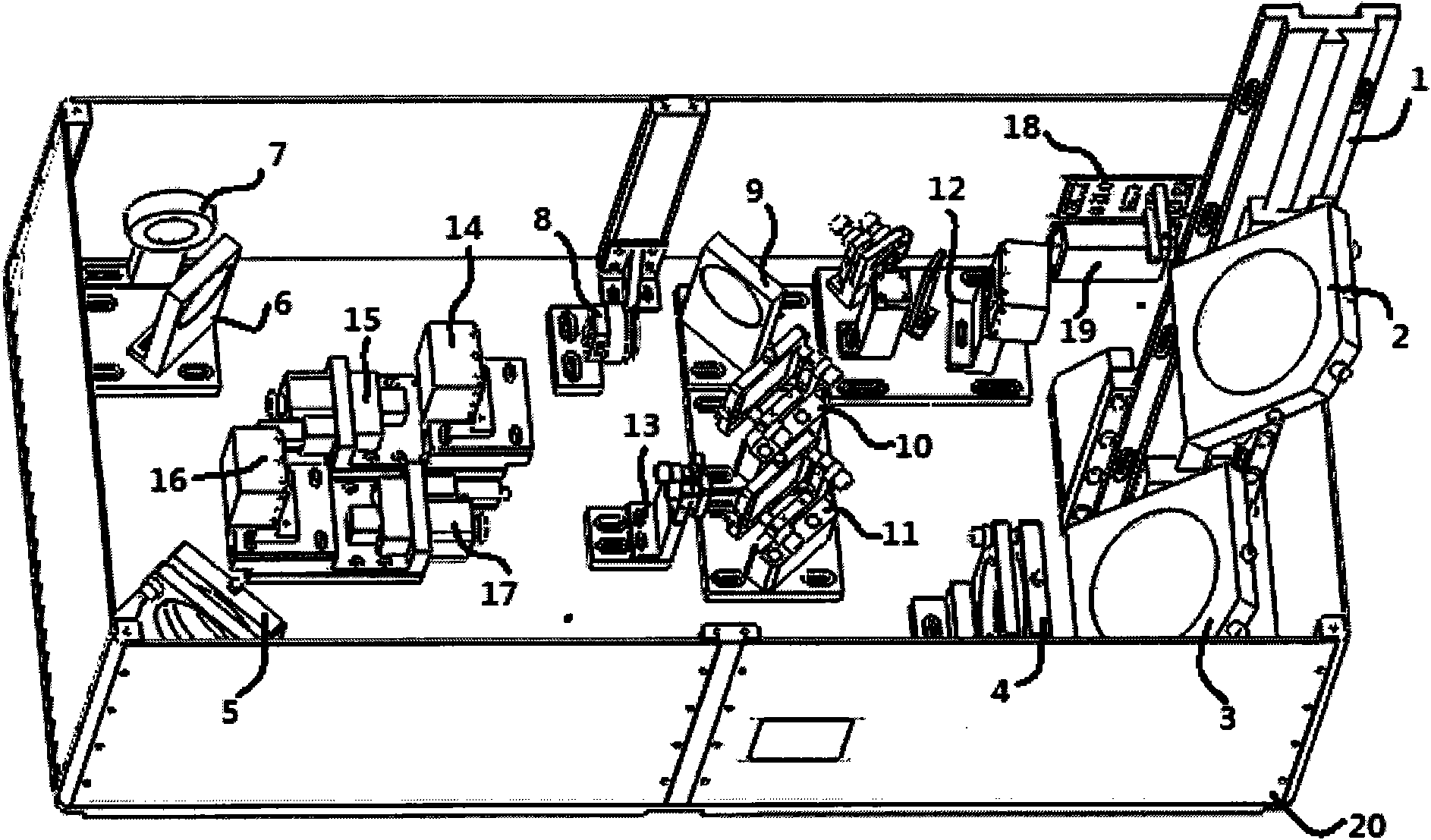
[0032] Such as figure 1 As shown, it is a structural schematic diagram of an embodiment of a laser multi-parameter real-time measurement system of the present invention, including a sliding strut 1, a front large reflector 1, a rear large reflector 2, a large lens 3, a large lens 4, a folding reflector 5, a front Fixed mirror 6, energy meter 7, rotating electromagnet 8, rear fixed mirror 9, front wedge 10, rear wedge 11, polarization test unit 12, small lens 13, far-field CCD 14, far-field electric translation stage 15, Near-field CCD16, near-field electric translation stage 17, interface circuit board 18, power supply module 19, box body 20, photoelectric probe 21 and spectrometer acquisition head 22. The internal structure of the system is as figure 1 shown.

[0033] When measuring, adjust the direction and angle of the incident beam of the instrument so that the laser beam to be measured is converged by the large lens 3 and then reflected by the folded reflector 5 and the...

Embodiment 2

[0036] The system includes a sliding strut 1, a front large reflector 1, a rear large reflector 2, a large lens 3, a large lens 4, a folding reflector 5, a front fixed reflector 6, a rear fixed reflector 9, a front wedge 10, a rear Wedge 11, small lens 13, far-field CCD14, far-field electric translation stage 15, near-field CCD16, near-field electric translation stage 17, interface circuit board 18, power supply module 19, box body 20.

[0037] When measuring, adjust the direction and angle of the incident beam of the instrument so that the laser beam to be measured is converged by the large lens 3 and reflected by the folding mirror 5 and the front fixed mirror 6, and most of it is reflected by the rear fixed mirror 9 and the front wedge 10. The rear wedge 11 splits the light and enters the far-field CCD14 and the near-field CCD16 respectively. Adjust the far-field electric translation stage 15 and the near-field electric translation stage 17 to find a clear image position, t...


PUM


Abstract

The invention relates to an apparatus for measuring multiple parameters of laser and belongs to the technical field of laser measurement. The apparatus is a measuring apparatus for laser, which comprises a computer, a power supply module, a reception module for a control signal, a front optical lens, a near-field optical lens, a scientific CCD, a near-field electric translation stage, a far-field electric translation stage, a photoelectric probe, a set of optical wedge plates, a set of reflectors, an attenuation slice and an energy meter. The measuring and calculating of the energy, the energy stability, the wavelength, the spectrum distribution, the pulse width, the pulse shape, the near-field light spot, the softening factor, the near-field modulation depth, the M2 factor, the divergence angle, the directivity, the output signal to noise ratio, the polarization direction, polarization degree, the beam waist location, the image transfer surface position, and the Rayleigh distance of monopulse laser can be realized through connecting the apparatus with relevant external measurement devices. The apparatus has the advantages of effectively improving measurement efficiency, calculating relevant parameters of a measured beam, and having practicality.

Description

technical field [0001] The invention relates to a novel laser measuring device, in particular to a laser parameter measuring device which integrates multiple instruments, and belongs to the technical field of laser measuring. Background technique [0002] In order to meet different needs, the output beam of a laser source needs to be measured in many aspects, such as: spectral width, spot size, spot modulation, Rayleigh distance, beam waist position, divergence angle, directivity, beam quality factor, Single pulse energy, energy stability, average power, power stability, repetition frequency, pulse width, pulse stability, output signal-to-noise ratio, polarization direction, polarization degree, etc. However, the existing laser parameter testing instruments can only test a single or closely related laser parameters, and cannot measure multiple parameters simultaneously and comprehensively across multiple aspects such as time domain, frequency domain, and energy. This makes ...

Claims


Application Information

Patent Timeline
Patent Type & Authority Applications(China)
IPC IPC(8): G01J11/00G01J9/00G01J3/28G01J1/42G01B11/00G01B11/08
Inventor 赵天卓樊仲维余锦刘洋张雪
Owner ACAD OF OPTO ELECTRONICS CHINESE ACAD OF SCI
Why Eureka
Try Eureka