Transformer substation capacitor on-line monitoring method and device based on wireless mode

A technology for substations and capacitors, applied in measuring devices, measuring resistance/reactance/impedance, measuring electrical variables, etc., can solve the problems of large investment, fixed points at the same location, synchronous sampling, high operating and payment costs, etc., to reduce system costs , Avoid cable laying, strong anti-electromagnetic interference

Active Publication Date: 2012-09-19
山东惠工电气股份有限公司
View PDF8 Cites 32 Cited by
  • Summary
  • Abstract
  • Description
  • Claims
  • Application Information

AI Technical Summary

Problems solved by technology

[0008] The technical problem to be solved by the present invention is: to realize the continuous and real-time online monitoring of the capacitance and dielectric loss parameters of all capacitors of the substation power compensation capacitor bank; to solve the problem that the compensation capacitor operates in a high-voltage state, and its working current sampling must meet the requirements of the power regulations The problem of insulation safety; solve the problems of large investment and high operating payment costs that may be brought about by adding a large number of network communication modules and GPS modules to the compensation capacitor current and voltage detection units, and solve the problems of low power consumption and long-term, continuous power supply; solve The measured voltage and measured current of the compensation capacitor must be fixed at the same position and sampled synchronously; provide a substation capacitance online monitoring method and device suitable for a large number of compensation capacitor banks installed in a substation

Method used


Image

  • Transformer substation capacitor on-line monitoring method and device based on wireless mode
  • Transformer substation capacitor on-line monitoring method and device based on wireless mode
  • Transformer substation capacitor on-line monitoring method and device based on wireless mode

Examples


Embodiment Construction

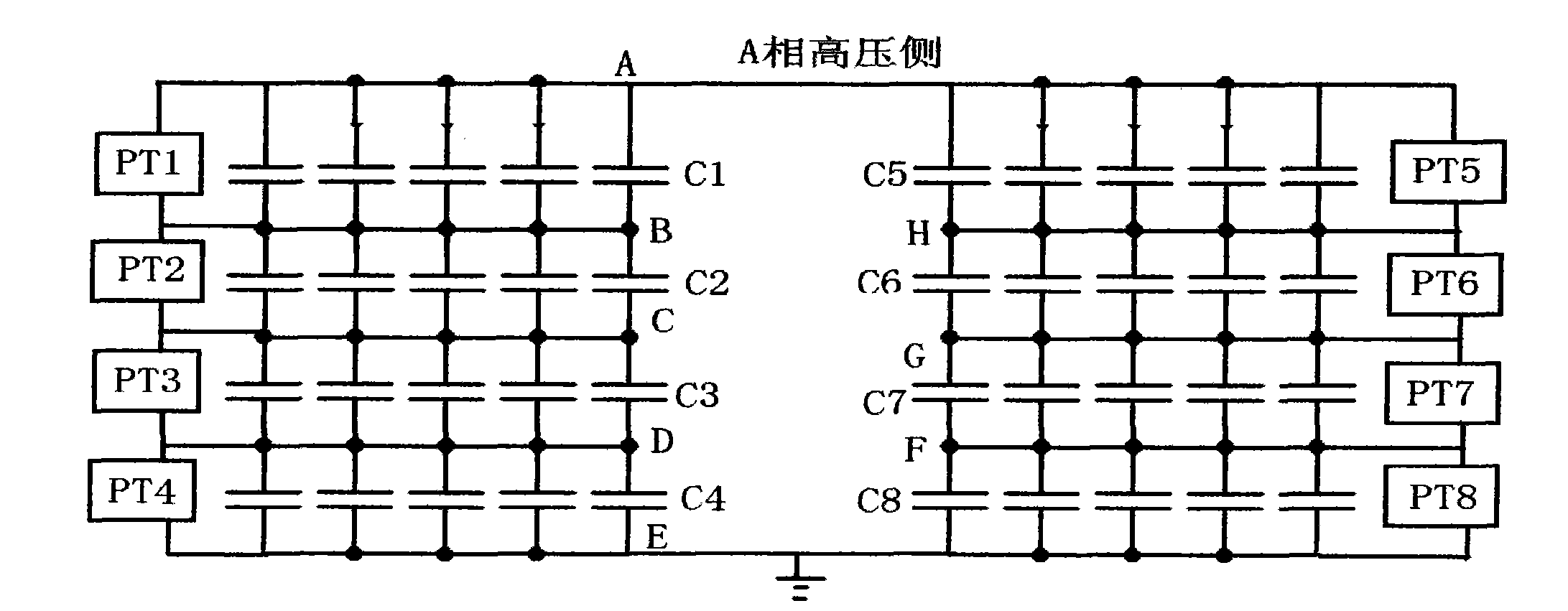
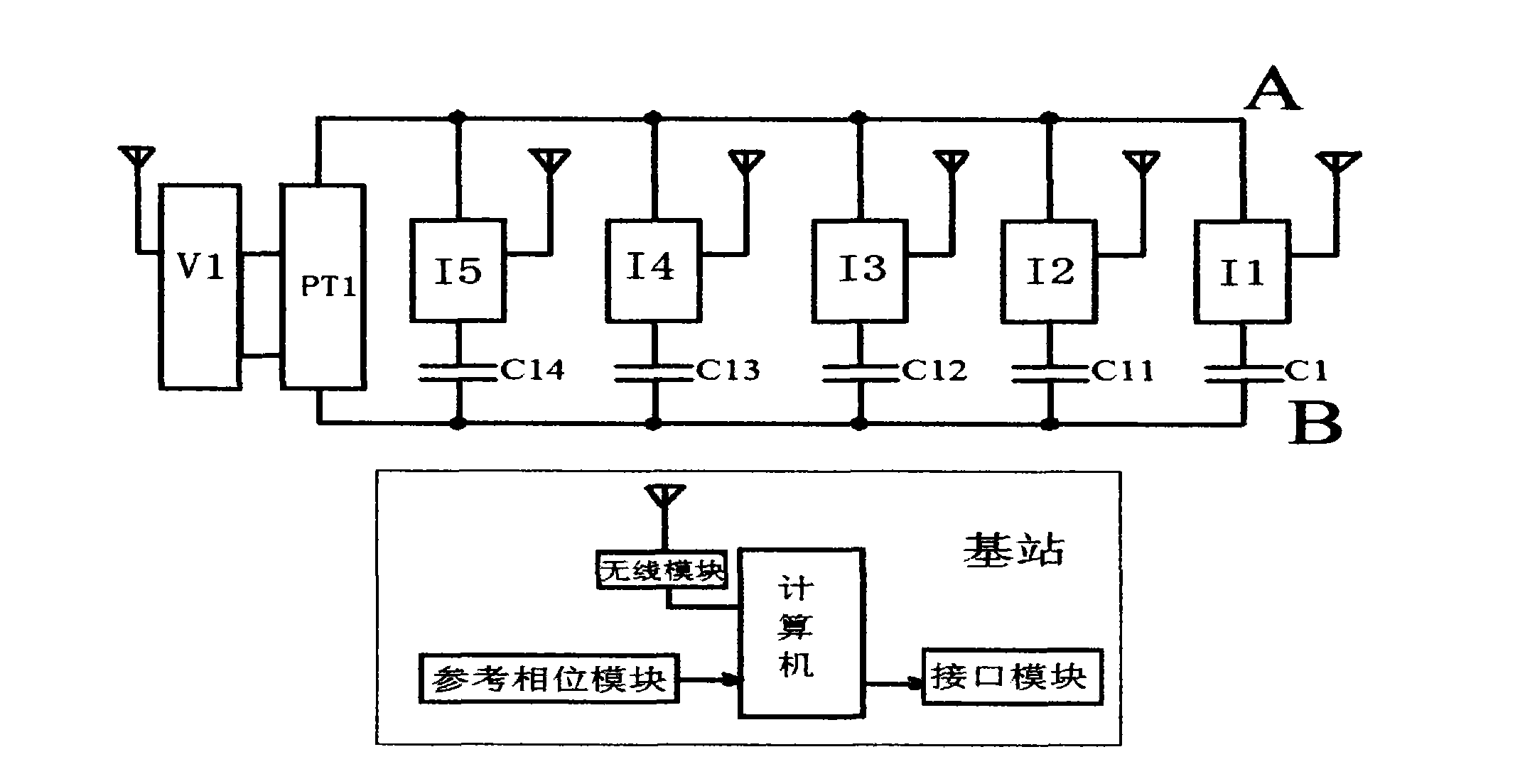
[0036] figure 1 It is a schematic diagram of the structure of a compensation capacitor bank in a 500KV substation. Only phase A compensation capacitors are shown in the figure, the structure of phase B and phase C compensation capacitors is the same as that of phase A, and there are 40 phase A capacitors, so there are 120 compensation capacitors in total for three phases. The voltage on the high-voltage side of phase A is 35KV, and there are 5 columns of capacitors on the left. Take the first column on the right as an example. Since the power capacitor is directly connected to the transmission line, the measured capacitors at points A and B are in a high-voltage state to the ground (E point), based on the consideration of insulation safety, we cannot connect the voltage signal to the current measurement unit in a high-voltage state by wire, and in order to ensure the stability of the measurement results obtained after FFT (fast Fourier transform) calculation, Each sampling mu...


PUM


Abstract

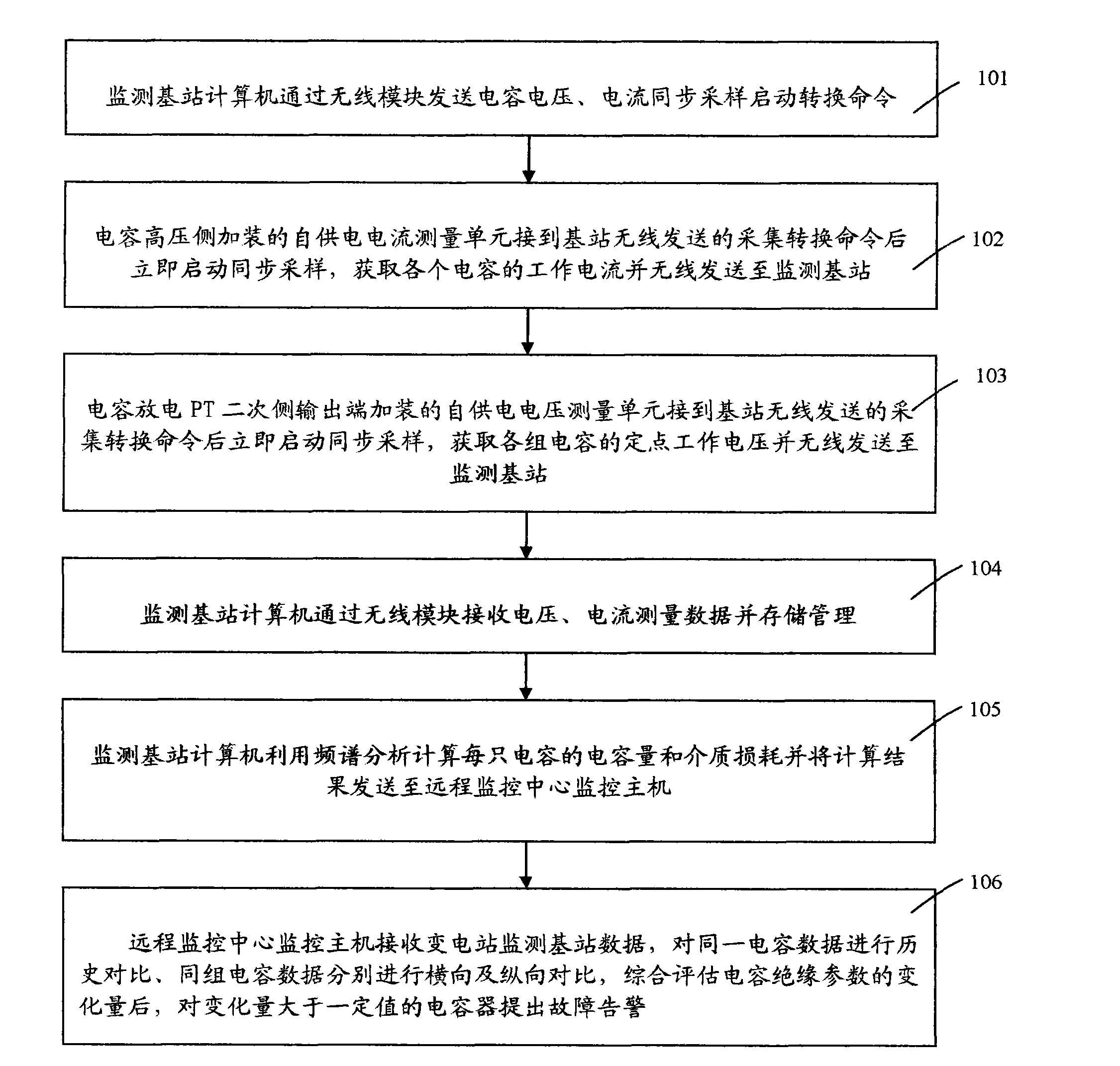
The invention belongs to the technical field of electric power equipment on-line monitoring, and in particular relates to a transformer substation capacitor on-line monitoring method and device based on a wireless mode, wherein the method mainly comprises the following steps: designing and additionally arranging a self-electricity-supplying current measuring unit at the high-voltage side of each capacitor, additionally arranging a self-electricity-supplying voltage measuring unit at the secondary side output end of an electricity discharge PT (potential transformer) of each group of parallel capacitors, acquiring the working voltage and current of each capacitor, and sending the obtained working voltage and current of each capacitor wirelessly to a monitoring base station; monitoring an internally-built computer and a wireless module of the base station; sending a capacitor voltage and current synchronous sampling starting conversion command, receiving, storing and managing measurement data, calculating the capacitance and medium loss of each capacitor by utilizing spectrum analysis, sending the calculated result to a monitoring host machine of a remote monitoring center for comprehensive estimation and analysis, and giving out a fault alarm for the capacitors with the variation greater than a certain value.

Description

technical field [0001] The invention belongs to the technical field of on-line monitoring of electric power equipment, and in particular relates to a method and a device for on-line monitoring of substation capacitance based on a wireless mode. Background technique [0002] Shunt capacitors are widely used in reactive power compensation of power systems, and are generally installed in substations for centralized compensation. The capacitor bank structure of a 500KV substation is as follows: figure 1 shown. With the increasing scale of the power grid and the increasing load demand, the system adjusts its voltage and reactive power more and more frequently. The safe operation of parallel capacitor banks plays a very important role in the stable and normal power supply of the entire power system. When a capacitor in the frame-type capacitor group is damaged and the entire group of capacitors trips, other capacitors may be damaged due to impact, and in severe cases, the capacit...

Claims


Application Information

Patent Timeline
Patent Type & Authority Applications(China)
IPC IPC(8): G01R27/26G08C17/02
Inventor 李洪景
Owner 山东惠工电气股份有限公司
Why Eureka
Try Eureka