
Annular track crane

A technology of circular track and crane, which is applied in the direction of crane, trolley crane, traveling mechanism, etc., can solve the problems of increased wear and tear of horizontal wheel, potential safety hazards, and increased gap between horizontal wheel and circular track, etc.

Pending Publication Date: 2018-02-27
HENAN DAFANG HEAVY MACHINERY
View PDF10 Cites 1 Cited by
  • Summary
  • Abstract
  • Description
  • Claims
  • Application Information

AI Technical Summary

Problems solved by technology

[0002] During the operation of the hoisting trolley of the ring rail crane, the wheels are likely to gnaw on the ring track. In addition, when the hoisting trolley runs along the ring track, it is also prone to derailment due to centrifugal force, causing potential safety hazards. Horizontal wheels are set on the frame to prevent rail gnawing and derailment through the cooperation between the horizontal wheels and the circular track. The effect of derailment becomes worse, thus causing safety hazards

Method used


Image

  • Annular track crane
  • Annular track crane
  • Annular track crane

Examples


Embodiment Construction

[0017] The present invention will be further described below in conjunction with accompanying drawing.

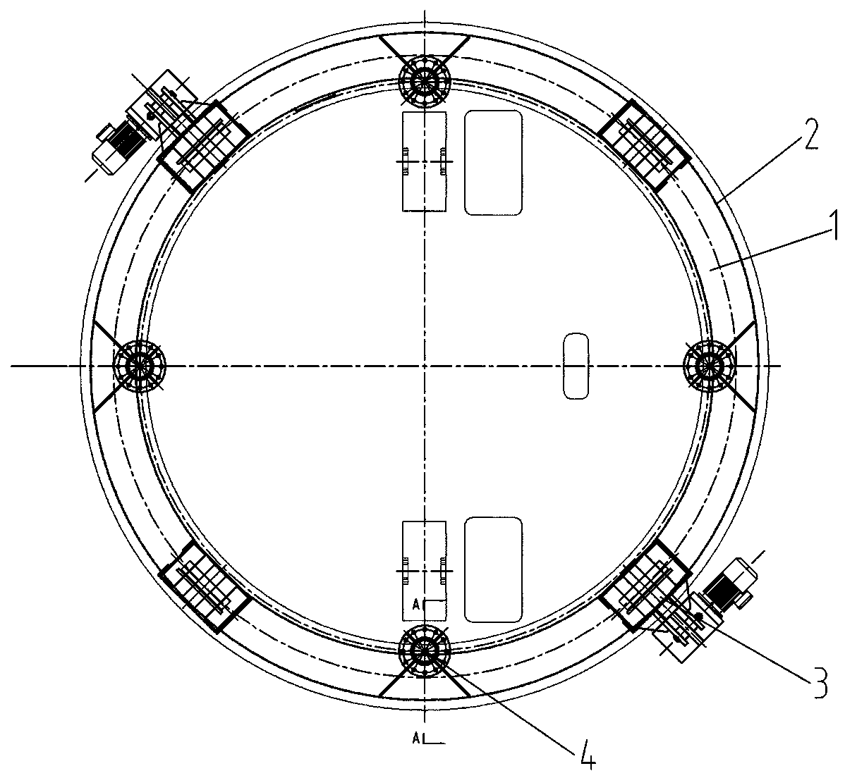
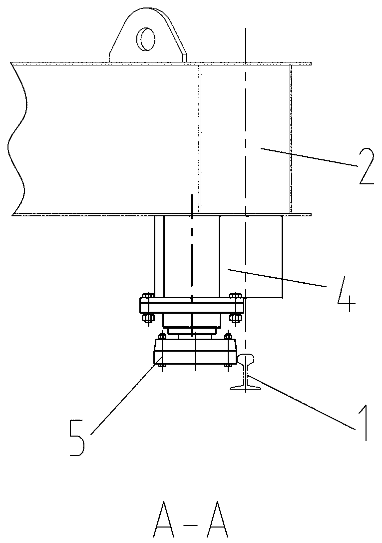
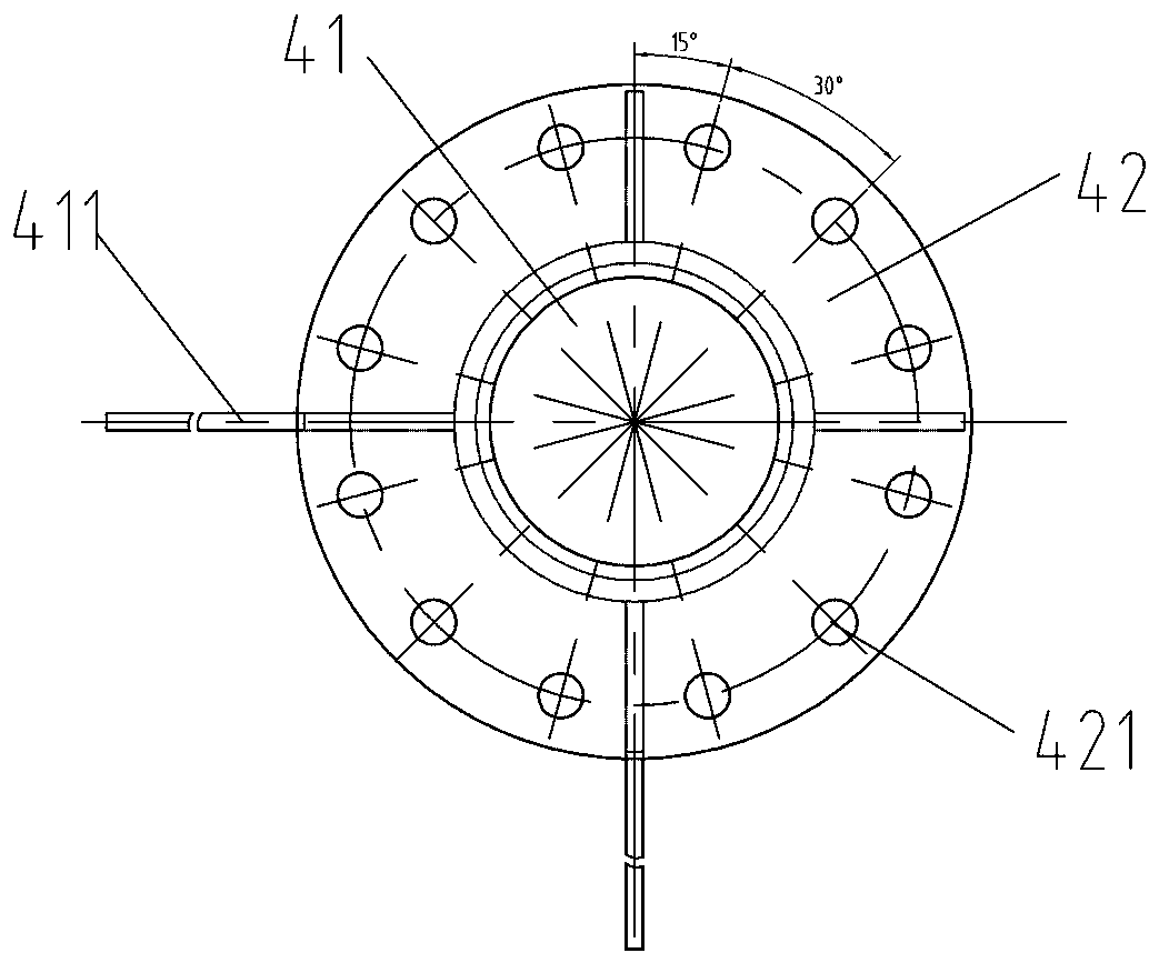
[0018] Specific embodiment one of the ring track crane of the present invention, as Figure 1 to Figure 4 As shown, it includes a ring track 1, a ring frame 2 and a lifting trolley 3, the ring frame 2 is compatible with the ring track 1, the lifting trolley 3 is fixedly connected with the ring frame 2 and can run along the ring track 1, the ring The vehicle frame 2 is connected with the horizontal wheel group 5 through the horizontal wheel group bracket 4. The horizontal wheel group bracket 4 includes a connecting part 41 and a bracket flange 42. The connecting part 41 is fixed on the ring frame 2, and the connecting part 41 and the bracket flange 42 Rotationally connected, the horizontal wheel set 5 includes a rotating shaft 51, a horizontal wheel 52 and a connecting flange 53, the lower end of the rotating shaft 51 is provided with a shaft shoulder 521, and the end of the...


PUM


Abstract

The invention provides an annular track crane which comprises an annular track, an annular frame and a crab. The annular frame is matched with the annular track. The crab is fixedly connected with theannular frame and can operate along the annular track. The annular frame is connected with a horizontal wheel set through a horizontal wheel set support, the horizontal wheel set support comprises aconnection portion and a support flange, the connection portion is fixed to the annular frame, the connection portion and the support flange are rotationally connected, the horizontal wheel set comprises a rotating shaft, a horizontal wheel and a connection flange, one end of the rotating shaft is rotationally connected with the horizontal wheel, the other end of the rotating shaft is eccentrically connected with the connection flange, and the connection flange and the support flange are fixedly connected. When the horizontal wheel is abraded when used for a long time, and the support flange is rotated so as to drive the connection flange to rotate. Since the rotating shaft and the connection flange are eccentrically arranged, the gap between the horizontal wheel and the track can be adjusted by rotating the connection flange, and therefore the crab is prevented from track biting or track disengagement.

Description

technical field [0001] The invention relates to the field of cranes, in particular to a ring track crane. Background technique [0002] During the operation of the hoisting trolley of the ring rail crane, the wheels are likely to gnaw on the ring track. In addition, when the hoisting trolley runs along the ring track, it is also prone to derailment due to centrifugal force, causing potential safety hazards. Horizontal wheels are set on the frame to prevent rail gnawing and derailment through the cooperation between the horizontal wheels and the circular track. The derailment effect becomes worse, thereby causing safety hazards. Contents of the invention [0003] The technical problem to be solved by the present invention is to provide a ring track crane capable of adjusting the gap between the horizontal wheel and the track. [0004] In order to achieve the above object, the technical solution adopted by the present invention is: a ring track crane, comprising a ring tra...

Claims


Application Information

Patent Timeline
Patent Type & Authority Applications(China)
IPC IPC(8): B66C19/00B66C9/04B66C9/08B66C9/16
CPCB66C9/04B66C9/08B66C9/16B66C19/00
Inventor 郭长宇李飞孙国庆聂永硕王利
Owner HENAN DAFANG HEAVY MACHINERY
Learn More