Pedal correction mechanism for elliptical trainer

a technology of elliptical trainer and correction mechanism, which is applied in the field of elliptical trainer, can solve the problems of affecting user safety, affecting the safety of users, and the installation location of the rod end bearing cannot provide an accurate correction function, so as to reduce noise, avoid derailment, and eliminate cumulative tolerances

Inactive Publication Date: 2014-08-19
DYACO INT INC
View PDF8 Cites 11 Cited by
  • Summary
  • Abstract
  • Description
  • Claims
  • Application Information

AI Technical Summary

Benefits of technology

[0007]The present invention has been accomplished under the circumstances in view. It is the main object of the present invention to provide a pedal correction mechanism for elliptical trainer, which effectively eliminate cumulative tolerances, avoiding derailment and reducing noises during the operation of the elliptical trainer /
[0008]To achieve this and other objects of the present invention, a pedal correction mechanism for elliptical trainer comprises a pedal link, a pedal bracket and a pedal. The pedal link comprises a coupling portion at an inner side thereof. The pedal bracket comprises a shaft pivotally inserted into the coupling portion of the pedal link for allowing the pedal bracket to be biased leftwards and rightwards on the axis of the shaft relative to the pedal link. The pedal is mounted at the top side of the pedal bracket for allowing a user to step thereon. By means of biasing of the pedal bracket leftwards and rightwards relative to the pedal link, cumulative tolerances among component parts can be eliminated, achieving the object of the present invention.

Problems solved by technology

However, the installation locations of the rod end bearings cannot provide an accurate correction function.
Under this condition, the cumulative tolerances among the component parts will also be guided to the rollers during the operation of the elliptical trainer, causing moving instability of the rollers and noises.
When it is more serious, the rollers may come off the sliding tracks, affecting user safety.

Method used


Image

  • Pedal correction mechanism for elliptical trainer
  • Pedal correction mechanism for elliptical trainer
  • Pedal correction mechanism for elliptical trainer

Examples


Embodiment Construction

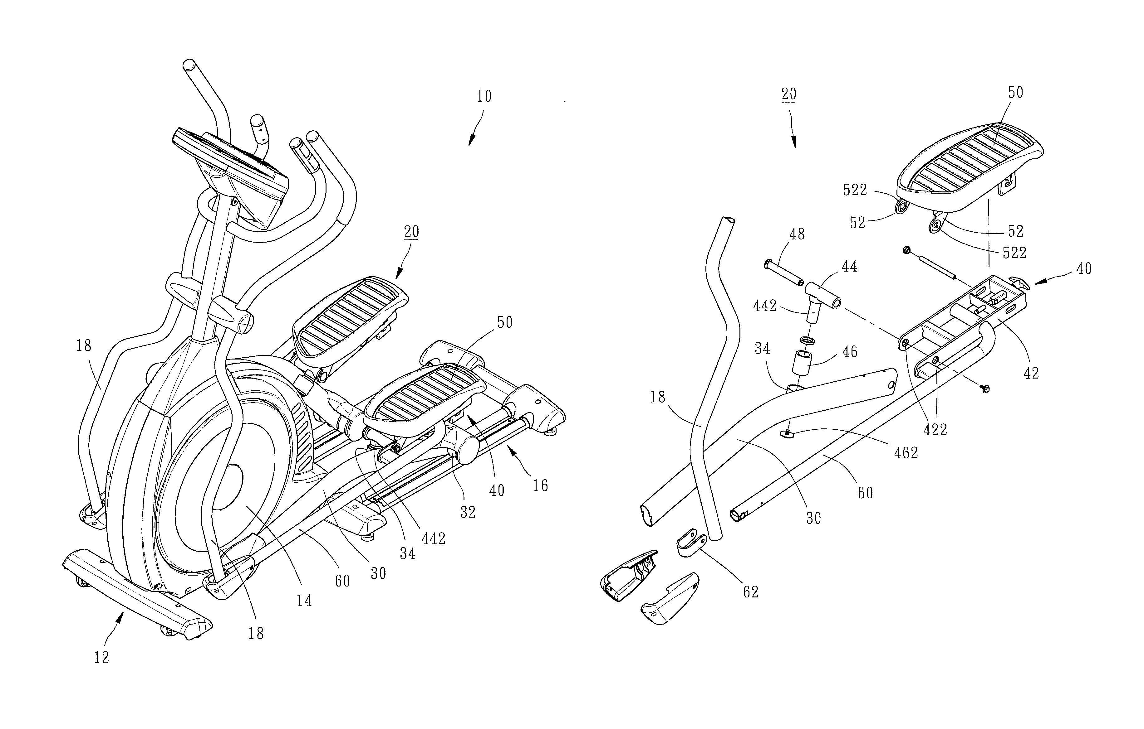
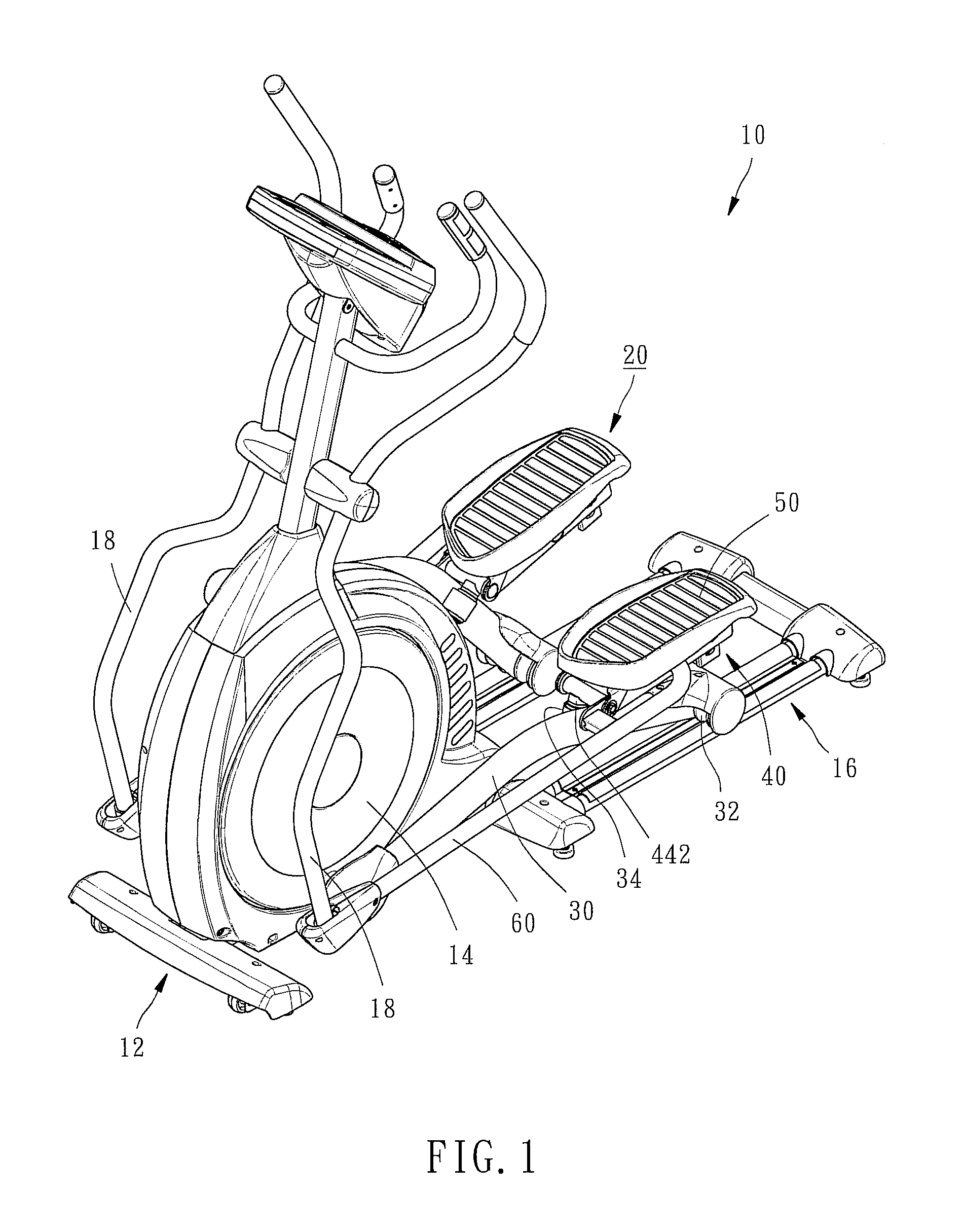
[0016]Referring to FIG. 1, an elliptical trainer 10 is shown comprising a base frame 12, a flywheel 14 rotatably mounted at the front side of the base frame 12, two sliding tracks 16 arranged in a parallel manner at the rear side of the base frame 12, and two swing rods 18 disposed at two opposite lateral sides relative to the flywheel 14.

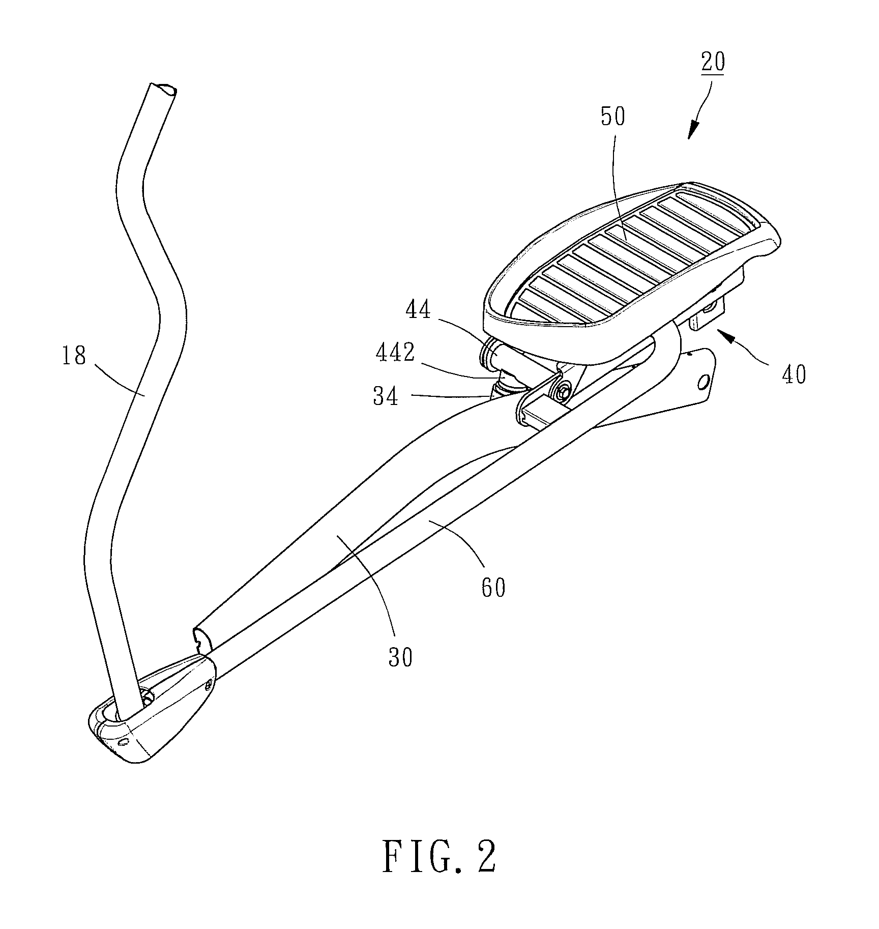
[0017]Referring to FIG. 2 and FIG. 1 again, the elliptical trainer 10 is equipped with a pedal correction mechanism 20. The pedal correction mechanism comprises two pedal link 30, two pedal brackets 40, two pedals 50, and two support tubes 60. As these two sets of component parts are identical, only one set of component parts will be explained hereinafter to save space.

[0018]The pedal link 30 has its front end coupled to the flywheel 14, and its rear end mounted with a roller 32 that is movable along one sliding track 16 of the elliptical trainer 10. Therefore, the pedal link 30 can be driven by the flywheel 14 to move the roller 32 back and forth ...


PUM


Abstract

A pedal correction mechanism used in an elliptical trainer is disclosed to include a pedal link having a coupling portion at the inner side thereof, and a pedal bracket carrying a pedal and having a shaft pivotally inserted into the coupling portion of the pedal link for allowing the pedal bracket to be biased leftwards and rightwards on the axis of the shaft relative to the pedal link to eliminate cumulative tolerances among component parts, preventing derailment and reducing noises.

Description

BACKGROUND OF THE INVENTION[0001]1. Field of the Invention[0002]The present invention relates to elliptical trainers and more particularly, to a pedal correction mechanism for elliptical trainer.[0003]2. Description of the Related Art[0004]An elliptical trainer is a recently developed cardio-respiratory fitness exercise machine for shuffling the feet back and forth within their elliptically shaped paths to simulate walking, running, or stair climbing without causing excessive pressure to the joints. Simply speaking, an elliptical trainer generally comprises two pedals, a flywheel, two pedal links coupled between the pedals and the flywheel, sliding tracks, a roller pivotally mounted at the rear side of each pedal and movable along one respective sliding track, and two swing rods respectively connected to the pedals by a respective support rod.[0005]Thus, when the user pedals the left and right pedals, the pedal links are moved to rotate the flywheel, and the rollers are moved with t...

Claims


Application Information

Patent Timeline
Patent Type & Authority Patents(United States)
IPC IPC(8): A63B22/04A63B21/22A63B22/00A63B22/06A63B22/12A63B22/20
CPCA63B22/04A63B21/225A63B22/001A63B22/203A63B22/0664
Inventor HUANG, HSUAN-FU
Owner DYACO INT INC
Why Eureka
Try Eureka