High Precision Syringe with Removable Pump Unit

a high-precision, pump unit technology, applied in the field of syringes, to achieve the effect of eliminating mechanical tolerances (“stacking”)

Active Publication Date: 2020-07-30
ZYNO MEDICAL
View PDF4 Cites 3 Cited by
  • Summary
  • Abstract
  • Description
  • Claims
  • Application Information

AI Technical Summary

Benefits of technology

[0006]The present invention provides a digital syringe that can be used with conventional polymer disposable syringe construction to be practical in the medical environment. Errors associated with the larger volumes of the syringes (which exacerbate minor errors in plunger position) and the flexibility and dimensional variations of the polymer plungers are by direct measurement of the syringe plunger position rather than indirect measurement of motor position and inference of syringe plunger position. This direct measurement eliminates mechanical tolerances (“stack up”) in the motor, gear train, and lead screw on plunger movement, an effect exacerbated by flexibility of the plunger and changes in syringe resistance and medicament viscosity, for example, with different medicaments or when the syringe is refrigerated. The digital syringe may be combined with the motor unit to provide additional versatility.

Problems solved by technology

Errors associated with the larger volumes of the syringes (which exacerbate minor errors in plunger position) and the flexibility and dimensional variations of the polymer plungers are by direct measurement of the syringe plunger position rather than indirect measurement of motor position and inference of syringe plunger position.

Method used


Image

  • High Precision Syringe with Removable Pump Unit
  • High Precision Syringe with Removable Pump Unit
  • High Precision Syringe with Removable Pump Unit

Examples


first embodiment

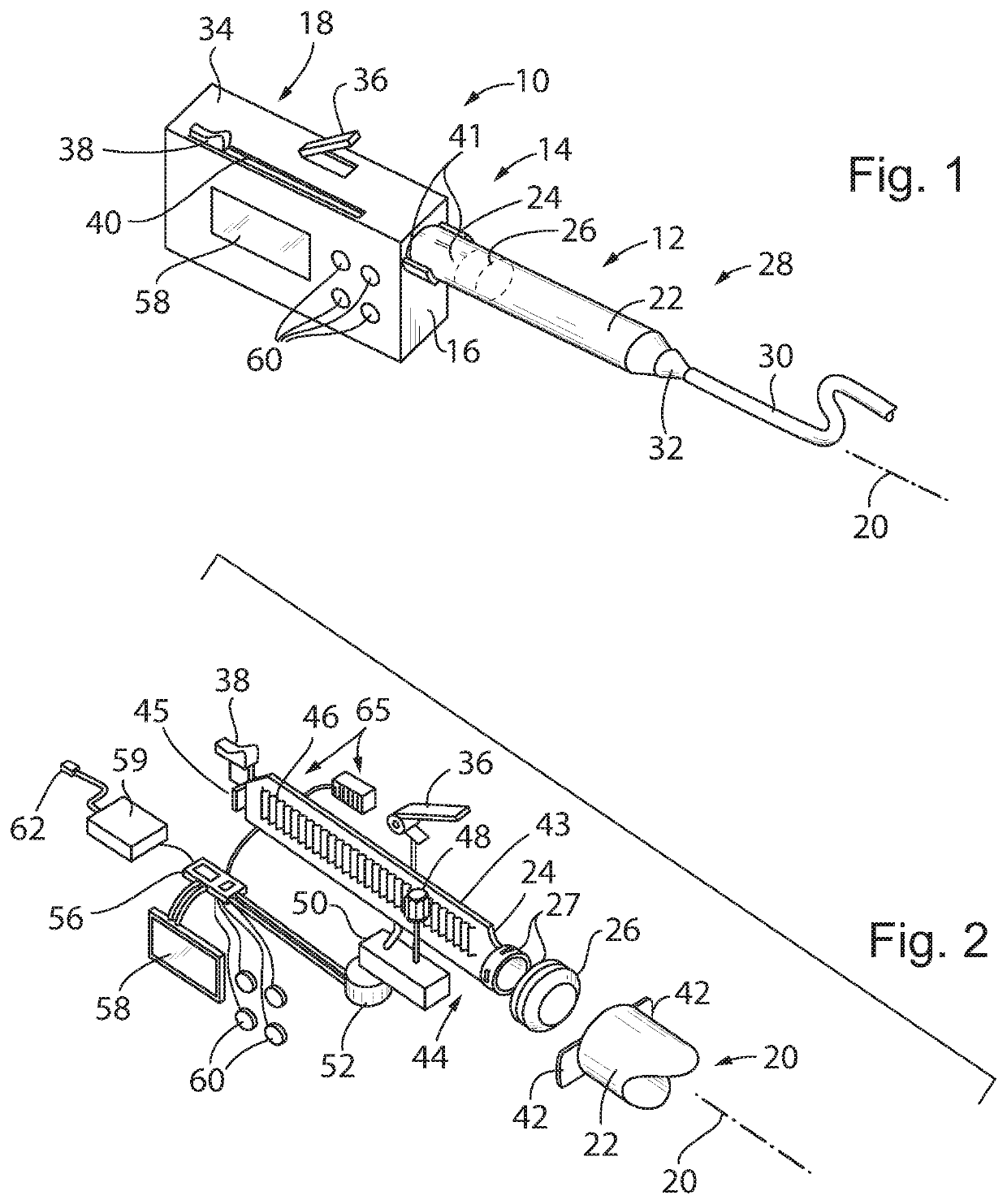
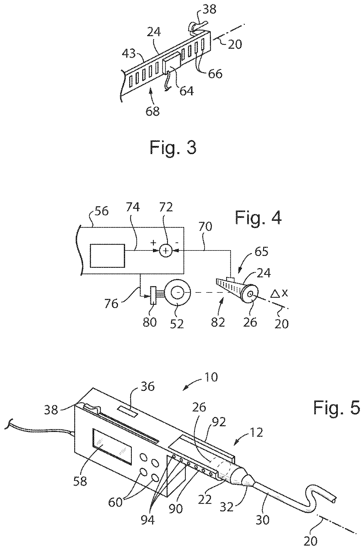
[0092]Referring now to FIG. 1, a syringe pump 10 of the present invention may employ a syringe unit 12 having a proximal end 14 attached to side wall 16 of a pump body 18 so that the syringe unit 12 extends generally along an axis 20.

[0093]The syringe unit 12 may be similar to a typical hypodermic syringe and having a syringe tube 22 open at the proximal end 14 to receive a plunger shaft 24 (partially visible in FIG. 1 through the syringe tube 22), the plunger shaft 24 extending away from the proximal end 14 into the pump body 18. The syringe tube 22 may be made of an injection molded inert, non-reactive syringe polymer such as polypropylene and the plunger shaft 24 may be made of an injection molded inert, non-reactive syringe polymer such as polyethylene. The end of the of the plunger shaft 24 within the syringe tube 22 is connected to a plunger piston 26, the latter, for example, being an elastomeric material such as rubber (partially visible through the syringe tube 22 in FIG. 1...

second embodiment

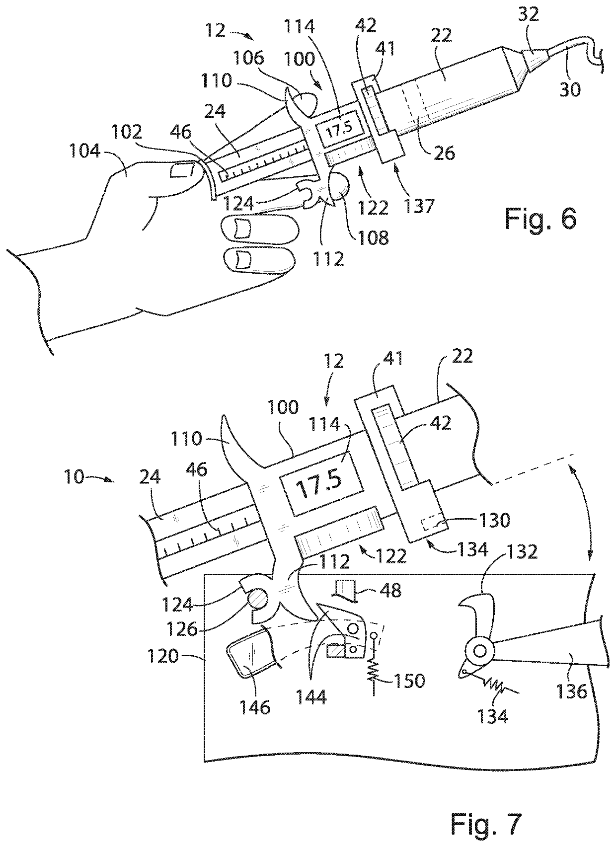
[0111]Referring now to FIGS. 6 and 7, a second embodiment of the pump 10 using the functional elements of the first embodiment except as noted may provide for a detachable syringe unit 12 having a self-contained syringe holder 100. The syringe holder 100 incorporates on its front side a twist-lock collar 41 that may receive a syringe tube 22 as discussed above in the first embodiment. As before, the syringe tube22 may provide a Luer connection 32 attaching to an IV line 30.

[0112]The syringe holder 100 may slidably receive therethrough the plunger shaft 24 and may provide a rack 46 or similar engagement mechanism to allow an internal pinion gear 48 (not shown but per the first embodiment) to move the plunger shaft 24 under the influence of a detachable motor unit as will be discussed below.

[0113]The distal end of the plunger shaft 24 may provide for a thumb button 102 for manual operation by a healthcare professional who may press on the thumb button 102 with a thumb 104 while having...

third embodiment

[0140]Referring now to FIGS. 19 and 20, a third embodiment of the pump 10 using the functional elements of the first and second embodiment except as noted may provide for a removable syringe unit 12 removably received within a pump housing 300. The pump housing 300 incorporates on its front side 301, a display screen 58 and various input buttons 60 as discussed above with respect to the first embodiment to provide display information to the user and to communicate various inputs to an internal controller microcontroller 56 allowing for control of the syringe unit 12. The input buttons 60 may be on a keypad or a liquid crystal display screen with virtual buttons such as those found on smart phones and tablets.

[0141]The syringe unit 12, attachable to the pump housing 300, includes a syringe tube 22 extending along an axis 20 and open at the proximal end 14 to receive a proximal end 15 of a plunger shaft 24, the plunger shaft 24 extending away from the proximal end 14 of the syringe tu...


PUM


Abstract

A digital syringe is used with conventional polymer disposable syringe construction to be practical in the medical environment. Errors associated with the larger volumes of the syringes (which exacerbate minor errors in plunger position) and the flexibility and dimensional variations of the polymer plungers are accommodated by direct measurement of the syringe plunger position rather than indirect measurement of motor position and inference of syringe plunger position. This direct measurement eliminates mechanical tolerances (“stack up”) in the motor, gear train, and lead screw on plunger movement, an effect exacerbated by flexibility of the plunger and changes in syringe resistance and medicament viscosity, for example, with different medicaments or when the syringe is refrigerated. The digital syringe may be combined with the motor unit to provide additional versatility.

Description

CROSS REFERENCE TO RELATED APPLICATION[0001]This application is a continuation-in-part of U.S. patent application Ser. No. 16 / 509,701, filed Jul. 12, 2019, which claims the benefit of U.S. Provisional Application No. 62 / 697,632, filed Jul. 13, 2018, and U.S. Provisional Application No. 62 / 799,475, filed Jan. 31, 2019, each of which are hereby incorporated by reference.BACKGROUND OF THE INVENTION[0002]The present invention relates to syringes as used for medical purposes, and in particular, to a syringe that provides improved precision.[0003]Syringes are known for administering medicaments, such as medicine or contrast agents, to a patient over a period of time. Such syringes include a plunger sliding in a syringe tube. The plunger includes a piston-like seal that fits tightly against the inner surface of the syringe tube. Movement of the plunger decreases the volume contained in the syringe tube between the plunger seal and an outlet of the syringe tube to provide a positive displac...

Claims


Application Information

Patent Timeline
Patent Type & Authority Applications(United States)
IPC IPC(8): A61M5/315A61M5/145A61M5/31A61M5/172
CPCA61M5/31556A61M5/31546A61M5/172A61M5/31515A61M5/3137A61M2205/3331A61M5/1456A61M5/31505A61M5/3158A61M5/14566A61M2005/3139A61M2005/31588A61M5/31568A61M5/20A61M2205/502A61M2205/3327A61M2205/3317A61M2205/3561A61M2205/60A61M2005/16863A61M2205/6072
Inventor LEE, CHAO YOUNGMAO, ZHENHUAZHANG, MEILEE, FREDERICK
Owner ZYNO MEDICAL
Why Eureka
Try Eureka