Ground clearance maintaining mechanism for to-ground photographing camera

A technology for holding mechanisms and cameras, which is applied in the field of omnidirectional vehicles, and can solve problems such as limited, inability to obtain clear and effective images, and inability to adjust the focus range of the camera

Active Publication Date: 2018-03-02
BEIJING INST OF SPECIALIZED MACHINERY
View PDF10 Cites 0 Cited by
  • Summary
  • Abstract
  • Description
  • Claims
  • Application Information

AI Technical Summary

Problems solved by technology

[0002] Due to their inherent characteristics, many cameras cannot focus or have a limited focus range. When the camera is too close to the object, a clear and effective image cannot be obt

Method used


Image

  • Ground clearance maintaining mechanism for to-ground photographing camera
  • Ground clearance maintaining mechanism for to-ground photographing camera
  • Ground clearance maintaining mechanism for to-ground photographing camera

Examples


Embodiment Construction

[0017] In order to make the purpose, content, and advantages of the present invention clearer, the specific implementation manners of the present invention will be further described in detail below in conjunction with the accompanying drawings and embodiments.

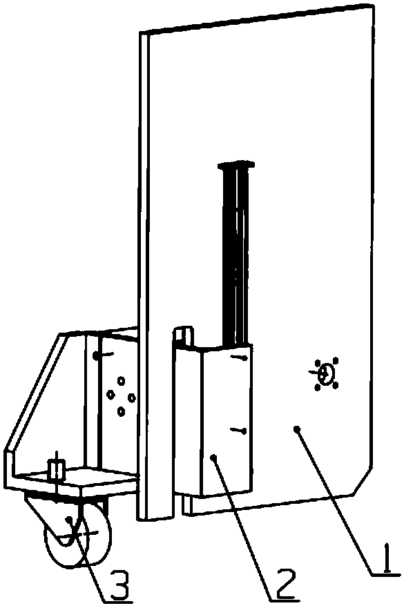
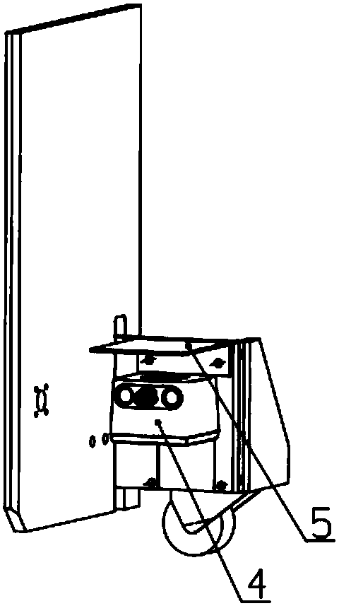
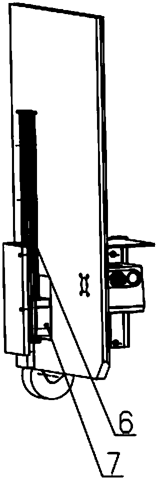
[0018] Such as Figure 1 to Figure 5 As shown, the present invention provides a ground-to-ground distance maintenance mechanism for a ground-to-ground camera, including: a slider mounting plate 1, a main body mounting plate 2, universal casters 3, a ground-to-ground camera 4, a camera baffle 5, and a linear guide rail 6 and a slider 7; wherein, the slider 7 is screwed on the slider mounting plate 1, and the main body mounting plate 2 is formed by screwing a plurality of flat plates or a single structural part, and the swivel caster 3, taking pictures on the ground Camera 4, camera baffle 5, and linear guide rail 6 are screwed on the main body mounting plate 2, and the installation positions of 3 universal casters, 4 pa...


PUM


Abstract

The invention relates to a ground clearance maintaining mechanism for a to-ground photographing camera, and relates to the technical field of omnidirectional vehicle. According to the ground clearancemaintaining mechanism for the to-ground photographing camera, the distance between the to-ground photographing camera and the ground can be kept unchanged through ingenious structural design, and thecamera can move freely in two directions.

Description

technical field [0001] The invention relates to the technical field of omnidirectional vehicles, in particular to a mechanism for maintaining a ground distance of a ground-facing camera. Background technique [0002] Due to their inherent characteristics, many cameras cannot focus or have a limited focus range. When the camera is too close to the object, a clear and effective image cannot be obtained. Therefore, it is necessary to keep the distance between the camera and the object not too close during dynamic movement. , which requires a distance maintaining mechanism to achieve. Contents of the invention [0003] (1) Technical problems to be solved [0004] The technical problem to be solved by the present invention is: how to design a ground-to-ground distance maintaining mechanism of the ground-facing camera so as to keep the distance between the camera and the ground from being too close during the dynamic movement. [0005] (2) Technical solutions [0006] In orde...

Claims


Application Information

Patent Timeline
IPC IPC(8): F16M11/18F16M11/42
Inventor 梁嘉震段三军李波李远桥
Owner BEIJING INST OF SPECIALIZED MACHINERY
Why Eureka
Try Eureka