Anchor stock mechanical response test device under dynamic and static combined load and using method thereof

A technology of combined load and testing device, which is applied in the direction of measuring device, testing material strength by applying repetitive force/pulsation force, testing material strength by applying stable tension/compression, etc., which can solve the weight, height and swing of the hammer The hammer angle range is limited, the size of the impact energy is limited, and the test results are difficult to provide accurate basis for the site, etc., to overcome the limitations of the test, the test results are stable, and the test results are accurate.

Active Publication Date: 2018-03-02
SHANDONG UNIV OF SCI & TECH
View PDF8 Cites 22 Cited by
  • Summary
  • Abstract
  • Description
  • Claims
  • Application Information

AI Technical Summary

Problems solved by technology

[0004] Existing bolt (cable) testing equipment and methods mostly test the mechanical response of the bolt (cable) under the action of pure static load or pure dynamic load, and it is difficult to obtain However, in the field engineering, the bolt has been subjected to a certain static load before being disturbed by the dynamic load, which makes it difficult for the test results to provide accurate basis for the field.
Moreover, the existing test equipment is mostly aimed at the mechanical performance test of a single bonded anchor rod under a single anchoring method (ie, end anchor), and it is difficult to test the mechanical properties of anchor rods under different types and different anchoring methods, and there are obvious limitations. sex
In addition,...

Method used


Image

  • Anchor stock mechanical response test device under dynamic and static combined load and using method thereof
  • Anchor stock mechanical response test device under dynamic and static combined load and using method thereof
  • Anchor stock mechanical response test device under dynamic and static combined load and using method thereof

Examples


Embodiment Construction

[0052] The preferred embodiments of the present invention will be described in detail below in conjunction with the accompanying drawings, so that the advantages and features of the present invention can be more easily understood by those skilled in the art, so as to define the protection scope of the present invention more clearly.

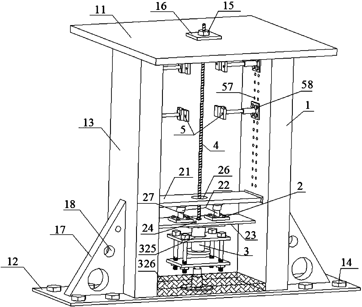
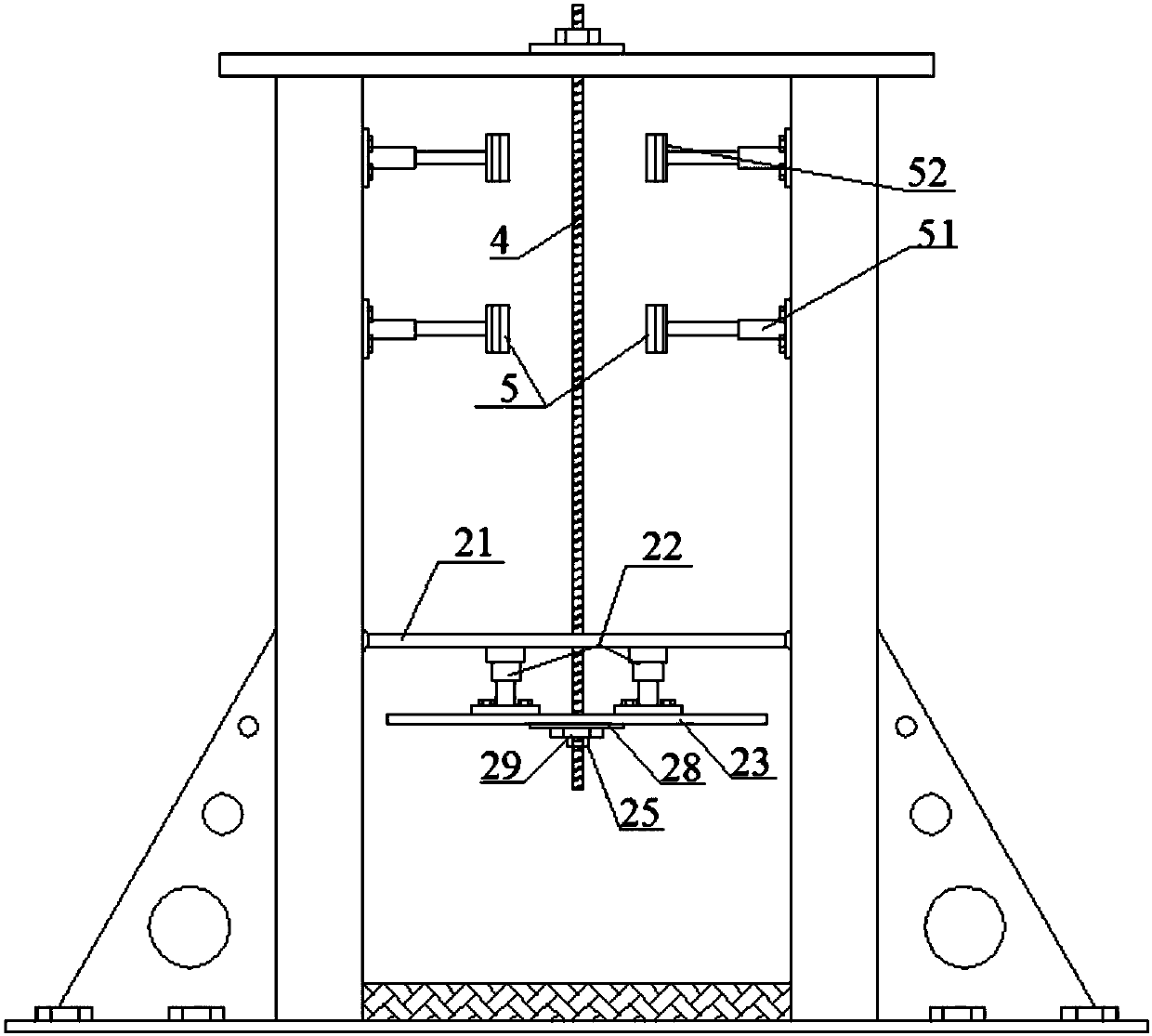
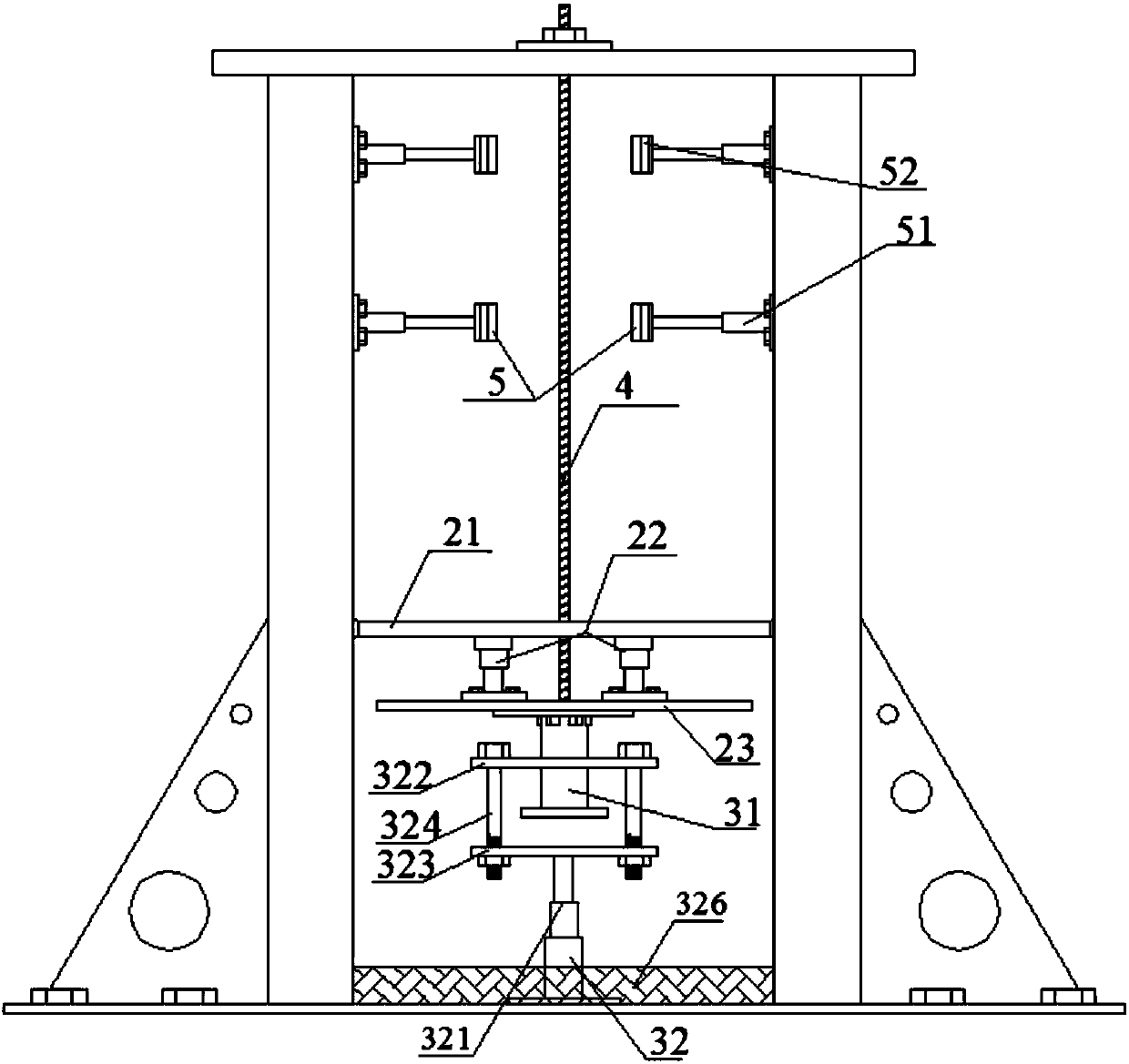
[0053] refer to Figure 1-3 As shown, the bolt testing device under dynamic and static combined loads of the present invention includes a vertical frame 1, a static load loading mechanism 2 and a dynamic loading mechanism 3, and the inside of the vertical frame 1 is provided with a bolt 4 to be tested, The upper end of the anchor rod 4 to be tested is fixedly connected to the top of the vertical frame 1, and its lower end extends vertically downward. connection, the static load loading mechanism 2 is used to apply static load to the anchor rod 4 to be tested, and the dynamic load loading mechanism 3 is arranged below the static load loading mecha...


PUM


Abstract

The invention discloses an anchor stock mechanical response test device under dynamic and static combined load and a using method thereof. The device comprises a vertical frame, a static loading mechanism and a dynamic loading mechanism. The vertical frame is provided therein with an anchor stock to be tested. The upper end of the anchor stock to be tested is fixedly connected with the top of thevertical frame. The lower end of the anchor stock to be tested extends vertically downwards. The static loading mechanism is disposed at the lower part of the vertical frame, is connected with the lower end of the anchor stock to be tested, and is configured to apply static load to the anchor stock to be tested. The dynamic loading mechanism is arranged below the static loading mechanism and configured to apply dynamic load to the anchor stock to be tested. The anchor stock mechanical response test device realizes a mechanical response test of the anchor stock to be tested under the combined dynamic and static load. The static load and the dynamic load can be controlled manually and can be adjusted in real time. In addition, the anchor stock mechanical response test device is simple, stable and reliable in test operation, and has great significance on the support design of deep mines and tunnels.

Description

technical field [0001] The invention relates to the technical field of mechanical response testing devices for bolts, in particular to a testing device for bolts under dynamic and static combined loads and a method for using the same. Background technique [0002] my country's coal reserves buried below 1000m are 2.95 trillion tons, accounting for about 53% of the total coal resources. Deep coal seams will surely become the main battlefield of my country's coal mining. According to incomplete statistics, more than 50 pairs of mines have been mined below 1,000 meters in my country. During the mining process, despite the adoption of greater support strength, accidents such as chipping, roof fall, and dynamic disasters such as rock bursts have increased significantly. , seriously restricting the safe and efficient mining of deep coal resources. [0003] Practice has shown that after entering deep mining, the phenomenon of dynamic load disturbance in the mine increases, and the ...

Claims


Application Information

Patent Timeline
IPC IPC(8): G01M13/00G01N3/02G01N3/10G01N3/307G01N3/36
CPCG01M13/00G01N3/02G01N3/10G01N3/307G01N3/36
Inventor 刘学生徐强谭云亮范德源宁建国
Owner SHANDONG UNIV OF SCI & TECH
Why Eureka
Try Eureka