An optical delay structure and device

An optical delay and reflection technology, applied in the field of optical delay, can solve the problems of pulse signal distortion and difficult data processing, etc., and achieve the effect of stable pulse signal, less distortion, and simple data processing

Active Publication Date: 2020-09-04
深圳市华讯方舟光电技术有限公司 +1
View PDF5 Cites 0 Cited by
  • Summary
  • Abstract
  • Description
  • Claims
  • Application Information

AI Technical Summary

Problems solved by technology

[0003] Based on this, it is necessary to provide an optical delay structure and device for the problems of pulse signal distortion and difficult data processing

Method used


Image

  • An optical delay structure and device
  • An optical delay structure and device
  • An optical delay structure and device

Examples


Embodiment Construction

[0019] In order to facilitate the understanding of the present invention, the present invention will be described more fully below with reference to the associated drawings. Preferred embodiments of the invention are shown in the accompanying drawings. However, the present invention can be embodied in many different forms and is not limited to the embodiments described herein. On the contrary, the purpose of providing these embodiments is to make the disclosure of the present invention more thorough and comprehensive.

[0020] Unless otherwise defined, all technical and scientific terms used herein have the same meaning as commonly understood by one of ordinary skill in the technical field of the invention. The terminology used herein in the description of the present invention is only for the purpose of describing specific embodiments, and is not intended to limit the present invention.

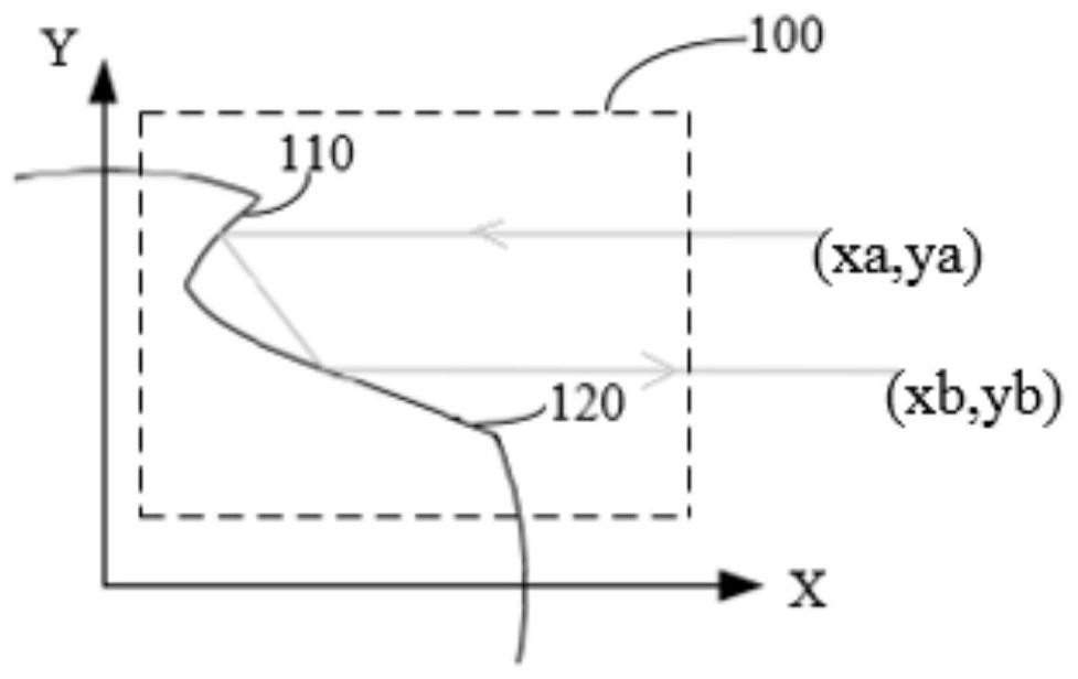
[0021] Such as figure 1 As shown, it is a schematic plan view of an optical retardati...


PUM


Abstract

An optical delay structure (100) and device. The optical delay structure (100) comprises a first reflective curved surface (110) and a second reflective curved surface (120), which are smoothly connected; the projection of the first reflective curved surface (110) on a set plane is a first curve, and the projection of the second reflective curved surface (120) on the same set plane is a second curve; the first curve and the second curve are smoothly connected, and the set plane is defined as an x-y plane. The first reflective curved surface (110) and the second reflective curved surface (120) satisfy the following: when light is incident on the first reflective curved surface (110) from a first position (xa, ya) outside of the delay structure (100) in a direction parallel to the x-y plane, the light is then reflected by means of the first reflective curved surface (110) onto the second reflective curved surface (120), and is emitted by means of the second reflective curved surface (120) to a second position (xb, yb) outside of the delay structure (100) in a direction parallel to the incident direction. An external drive structure drives the optical delay device to rotate at a constant speed such that the linearity of light delay following time may be obtained by means of the linearity of light delay following angle of rotation.

Description

technical field [0001] The invention relates to the field of optical delay, in particular to an optical delay structure and device. Background technique [0002] At present, the terahertz pulse signal width generated by the terahertz time-domain spectrometer is only a few picoseconds, and a femtosecond laser needs to be used to excite the semiconductor to sample the pulse signal. The arrival time of the femtosecond laser pulse to terahertz needs to be changed in order to collect the signal intensity at different positions of the terahertz pulse. The femtosecond laser passes through the delay line, which can change the optical path of the femtosecond laser. The linearity of the delay line will affect the accuracy and consistency of the collected signal. The nonlinear delay line will cause the femtosecond laser pulse optical path to change nonlinearly, and the collected signal will also be nonlinear, which will distort the terahertz pulse signal. Increase the difficulty of d...

Claims


Application Information

Patent Timeline
Patent Type & Authority Patents(China)
IPC IPC(8): G02B26/08
CPCG02B26/0816
Inventor 何坚兵潘奕丁俊侠丁庆
Owner 深圳市华讯方舟光电技术有限公司
Why Eureka
Try Eureka